System maintenance switch
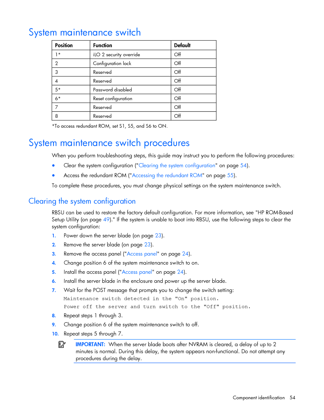
Position | Function | Default |
|
|
|
1* | iLO 2 security override | Off |
|
|
|
2 | Configuration lock | Off |
|
|
|
3 | Reserved | Off |
|
|
|
4 | Reserved | Off |
|
|
|
5* | Password disabled | Off |
|
|
|
6* | Reset configuration | Off |
|
|
|
7 | Reserved | Off |
|
|
|
8 | Reserved | Off |
|
|
|
*To access redundant ROM, set S1, S5, and S6 to ON.
System maintenance switch procedures
When you perform troubleshooting steps, this guide may instruct you to perform the following procedures:
•Clear the system configuration ("Clearing the system configuration" on page 54).
•Access the redundant ROM ("Accessing the redundant ROM" on page 55).
To complete these procedures, you must change physical settings on the system maintenance switch.
Clearing the system configuration
RBSU can be used to restore the factory default configuration. For more information, see "HP
1.Power down the server blade (on page 23).
2.Remove the server blade (on page 23).
3.Remove the access panel ("Access panel" on page 24).
4.Change position 6 of the system maintenance switch to on.
5.Install the access panel ("Access panel" on page 24).
6.Install the server blade in the enclosure and power up the server blade.
7.Wait for the POST message that prompts you to change the switch setting:
Maintenance switch detected in the "On" position.
Power off the server and turn switch to the "Off" position.
8.Repeat steps 1 through 3.
9.Change position 6 of the system maintenance switch to off.
10.Repeat steps 5 through 7.
IMPORTANT: When the server blade boots after NVRAM is cleared, a delay of up to 2 minutes is normal. During this delay, the system appears
Component identification 54