8.Slide the drive into the drive bay, making sure to align the guide screws with the guide slots, until the drive snaps into place.
Figure 2-24 Sliding the External Drives into the Drive Cage
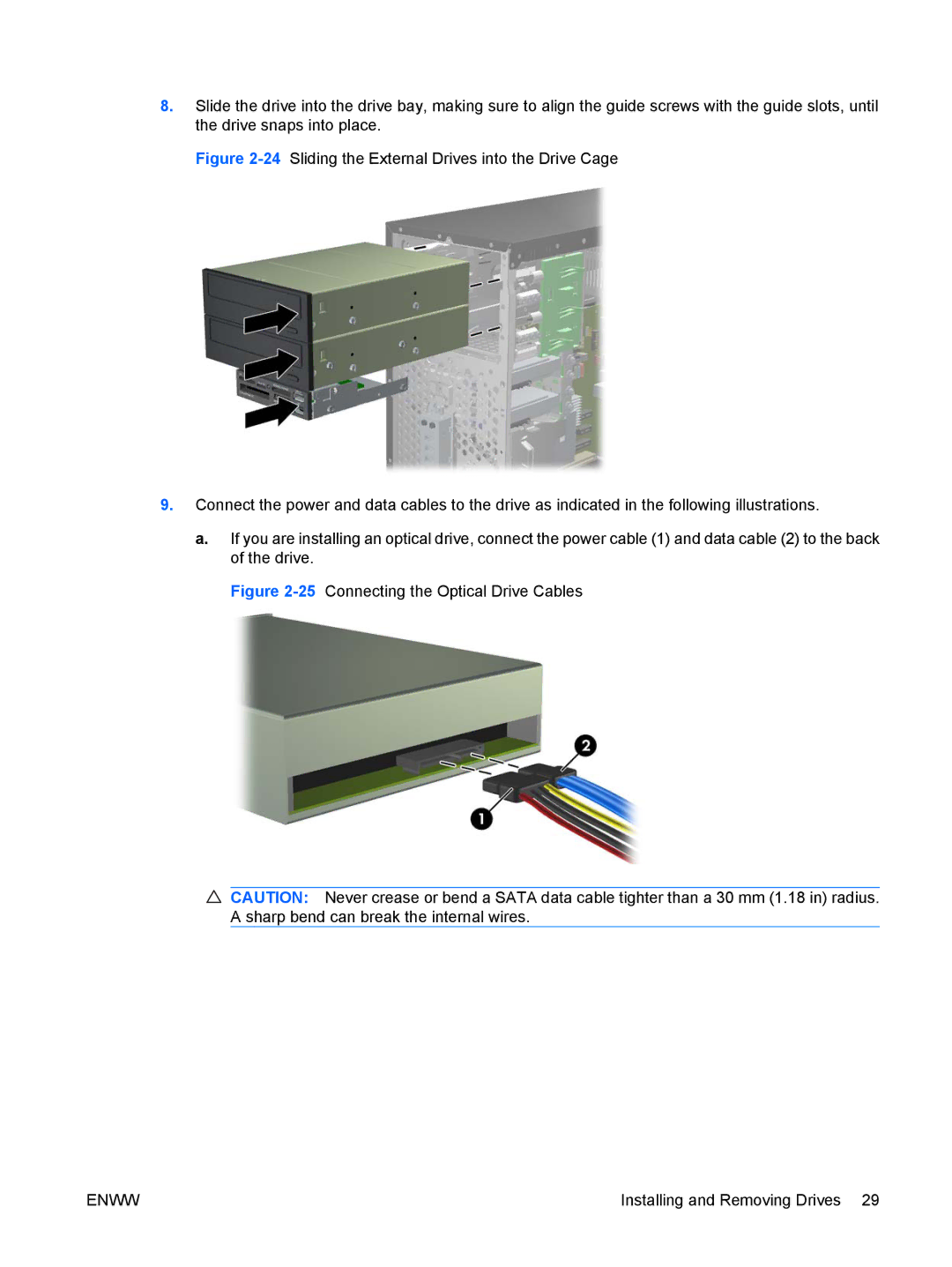
9.Connect the power and data cables to the drive as indicated in the following illustrations.
a.If you are installing an optical drive, connect the power cable (1) and data cable (2) to the back of the drive.
Figure 2-25 Connecting the Optical Drive Cables
![]() CAUTION: Never crease or bend a SATA data cable tighter than a 30 mm (1.18 in) radius. A sharp bend can break the internal wires.
CAUTION: Never crease or bend a SATA data cable tighter than a 30 mm (1.18 in) radius. A sharp bend can break the internal wires.
ENWW | Installing and Removing Drives 29 |