Installing an External 5.25-inch or 3.5-inch Drive
![]() NOTE: The system does not support Parallel ATA (PATA) optical drives.
NOTE: The system does not support Parallel ATA (PATA) optical drives.
1.Remove/disengage any security devices that prohibit opening the computer.
2.Remove all removable media, such as compact discs or USB flash drives, from the computer.
3.Turn off the computer properly through the operating system, then turn off any external devices.
4.Disconnect the power cord from the power outlet and disconnect any external devices.
![]() CAUTION: Regardless of the
CAUTION: Regardless of the
5.If you are installing a drive in a bay covered by a bezel blank, remove the front bezel then remove the bezel blank. See Removing Bezel Blanks on page 12 for more information.
6.Remove the access panel and front bezel.
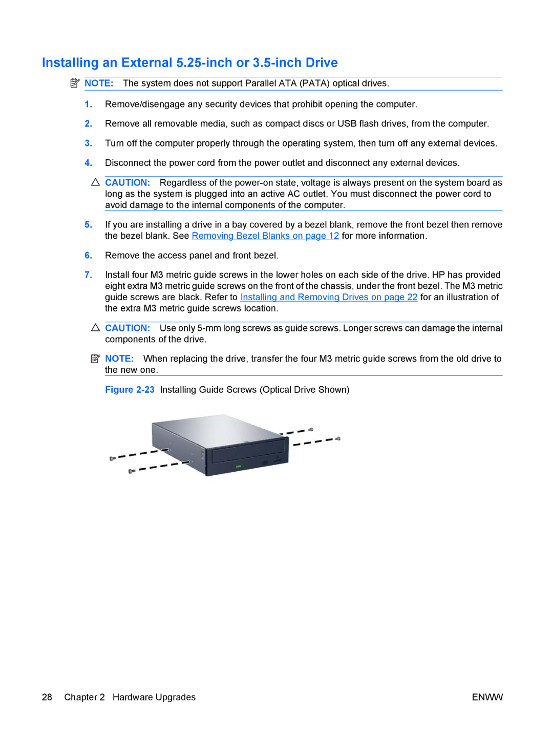
7.Install four M3 metric guide screws in the lower holes on each side of the drive. HP has provided eight extra M3 metric guide screws on the front of the chassis, under the front bezel. The M3 metric guide screws are black. Refer to Installing and Removing Drives on page 22 for an illustration of the extra M3 metric guide screws location.
![]() CAUTION: Use only
CAUTION: Use only
![]() NOTE: When replacing the drive, transfer the four M3 metric guide screws from the old drive to the new one.
NOTE: When replacing the drive, transfer the four M3 metric guide screws from the old drive to the new one.
Figure 2-23 Installing Guide Screws (Optical Drive Shown)
28 Chapter 2 Hardware Upgrades | ENWW |