LightHawk™ Wall Switch Occupancy Sensors
Installation and Operating Instructions
Hubbell Building Automation, Inc.
9601 Dessau Road, Building One, Suite 100 Austin, Texas 78754
Description
The LightHAWK is an intelligent
Specifications
•1000 sq. ft coverage area (Models: LHIR and LHMT)
•400 sq. ft. coverage area (Models: LHUS)
•Single or Dual circuit 120/277VAC, 50/60Hz operation
•Electrical Ratings: (Each Output Separately)
120VAC – 800W Incandescent, 1000W Ballast, 1/6 HP 277VAC – 1800W Ballast, 1/6 HP
•Adjustable Time Delay:
•Light Level Adjustment (Circuit B output on Dual Circuit versions):
•ETL listed (Conforms to UL STD 508 Certified to CAN/CSA STD C22.2 No. 14)
Precautions
CAUTION: RISK OF ELECTRICAL SHOCK. Turn power off at service panel before beginning installation. Never wire energized electrical components.
Read and understand all instructions before beginning installation.
NOTICE: For installation by a licensed electrician in accordance with National and/or local Electrical Codes and the following instructions.
NOTICE: For indoor use only.
CAUTION: USE COPPER CONDUCTOR ONLY.
Confirm that device ratings are suitable for application prior to installation.
NOTICE: Do not install if any damage to product is noticed.
Installation
1.Turn power off at the service panel.
2.Remove the old switch(es) if applicable.
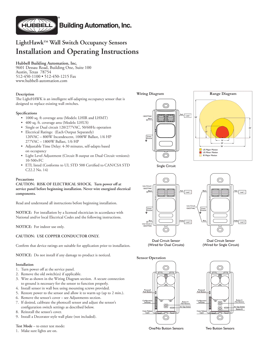
3.Wire as shown in the Wiring Diagram section. A secure connection to ground is necessary for the sensor to function properly.
4.Install sensor in wall box using mounting screws provided.
5.Restore power to the sensor and allow it to warm up (up to 2 min.).
6.Remove the sensor’s cover – see Adjustments section.
7.If desired, calibrate the photocell sensor and adjust the sensor’s configuration switch settings as described below.
8.Reinstall the sensor’s cover.
9.Install a Decorator style wall plate (not included).
Test Mode – to enter test mode: 1. Make sure lights are on.
Wiring Diagram
Sensor Operation
Range Diagram |