PIPING INSTALLATION
NOTE: The most effective means for preventing deterioration from accelerated corrosion due to galvanic and stray current is the installation of dielectric fittings/unions. The installation of these fittings is the responsibility of the installing contractor.
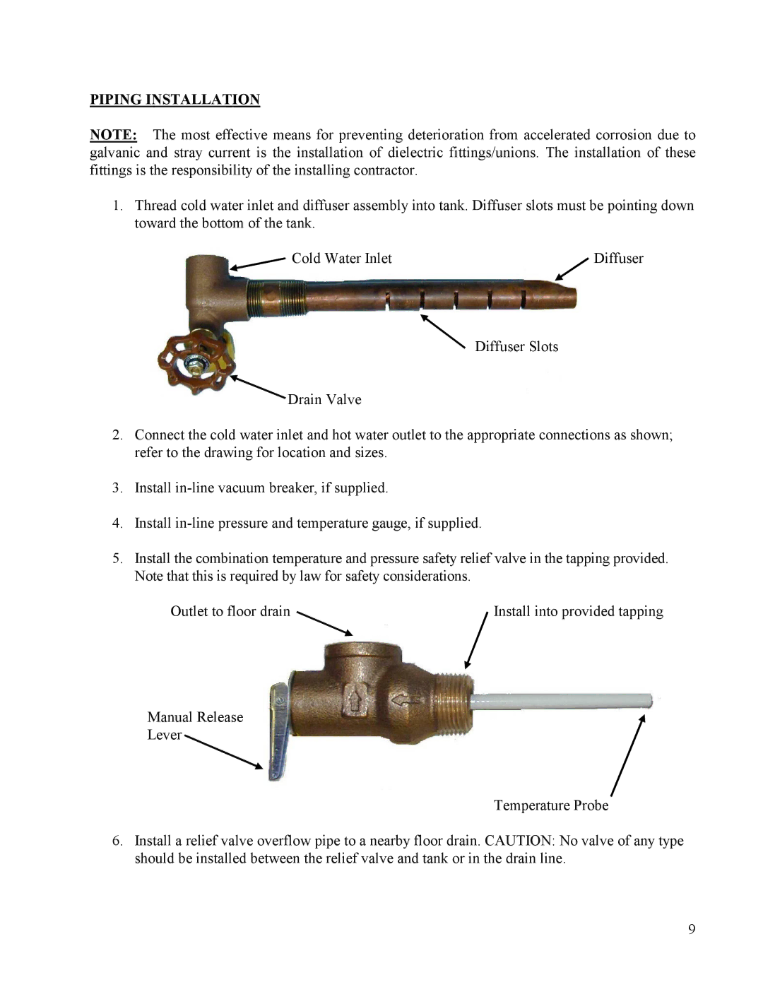
1.Thread cold water inlet and diffuser assembly into tank. Diffuser slots must be pointing down toward the bottom of the tank.
Cold Water Inlet | Diffuser |
Diffuser Slots
![]() Drain Valve
Drain Valve
2.Connect the cold water inlet and hot water outlet to the appropriate connections as shown; refer to the drawing for location and sizes.
3.Install
4.Install
5.Install the combination temperature and pressure safety relief valve in the tapping provided. Note that this is required by law for safety considerations.
Outlet to floor drain | Install into provided tapping |
Manual Release
Lever
Temperature Probe
6.Install a relief valve overflow pipe to a nearby floor drain. CAUTION: No valve of any type should be installed between the relief valve and tank or in the drain line.
9