•All
•To minimize heat loss and maximize efficiency, hot water piping should be insulated.
•Teflon tape should be used on all NPT threaded pipe connections.
1.Connect the cold/warm water inlet and hot water outlet to the appropriate connections as shown; refer to the specifications for location and sizes.
IMPORTANT – Be certain to connect the outlet piping to the final rinse and not to the wash tank. IMPORTANT (applies to J6 Models only) – Do not turn the entering warm water or exiting hot water nipples from their factory installed positions. The internal diffusers are aligned at the factory and turning the nipple will change the diffuser position and affect performance. Hubbell recommends that the inlet and outlet pipes are insulated to prevent excessive heat loss.
IMPORTANT (applies to J6 Models only) – Do not apply heat directly to the entering warm water or exiting hot water nipples. If sweat connections are to be used, sweat tubing to the adapter before threading the adapter to the nipple on the heater. Any heat applied to the heater nipple will damage the internal plastic diffuser and affect performance.
2.Install water pressure regulator and adjust to the pressure recommended by the dishwasher manufacturer. WHEN A STANDARD PRESSURE REGULATOR IS USED, (other than that purchased with the booster), it acts as a check valve and it is possible that thermal expansion will cause the relief valve to drip or occasionally blow off a small amount of water. To overcome this condition, it is recommended that a 3/8”
3.Install
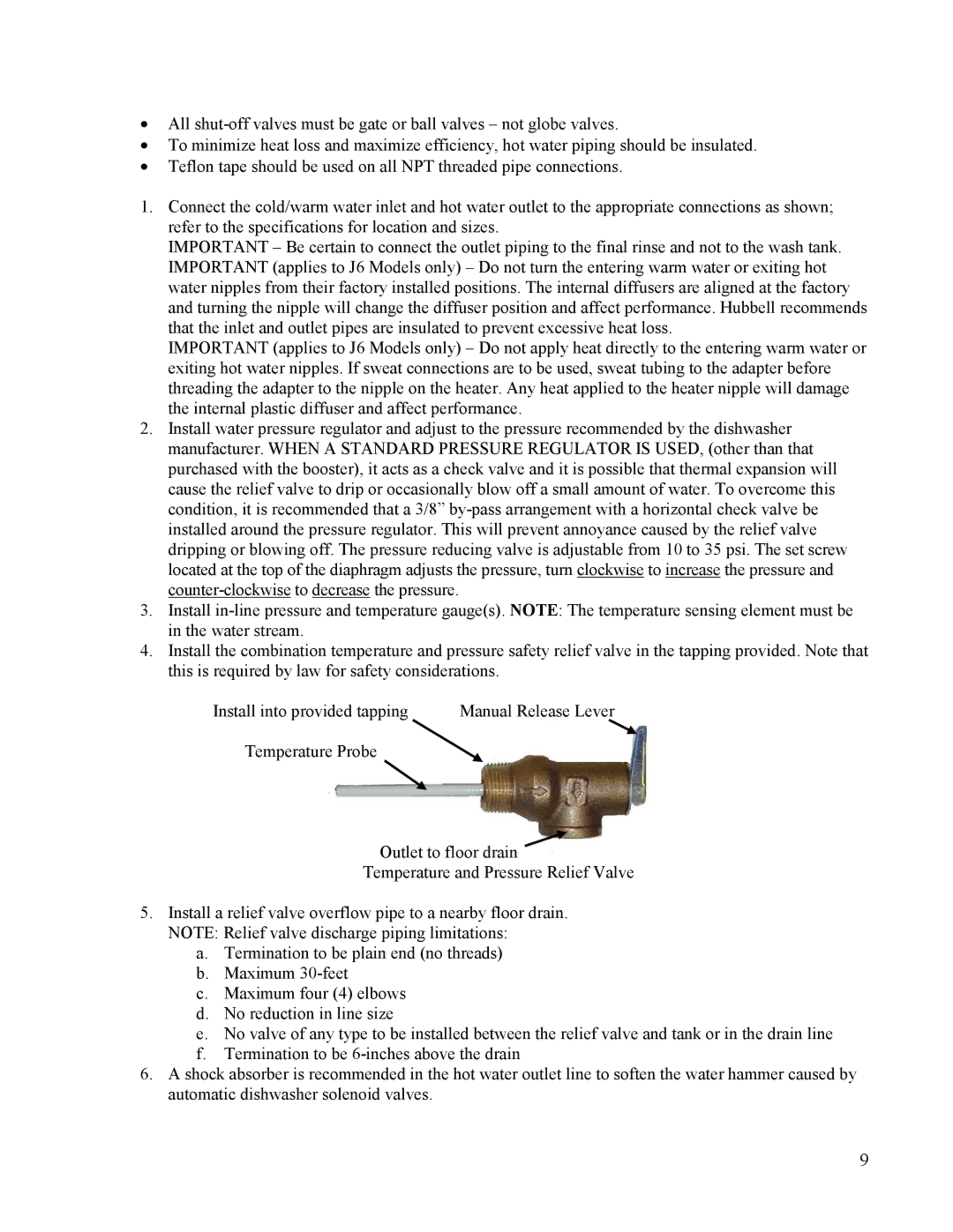
4.Install the combination temperature and pressure safety relief valve in the tapping provided. Note that this is required by law for safety considerations.
Install into provided tapping | Manual Release Lever |
Temperature Probe
Outlet to floor drain
Temperature and Pressure Relief Valve
5.Install a relief valve overflow pipe to a nearby floor drain. NOTE: Relief valve discharge piping limitations:
a.Termination to be plain end (no threads)
b.Maximum
c.Maximum four (4) elbows
d.No reduction in line size
e.No valve of any type to be installed between the relief valve and tank or in the drain line
f.Termination to be
6.A shock absorber is recommended in the hot water outlet line to soften the water hammer caused by automatic dishwasher solenoid valves.
9