32
1
9 8
7
31
29
28
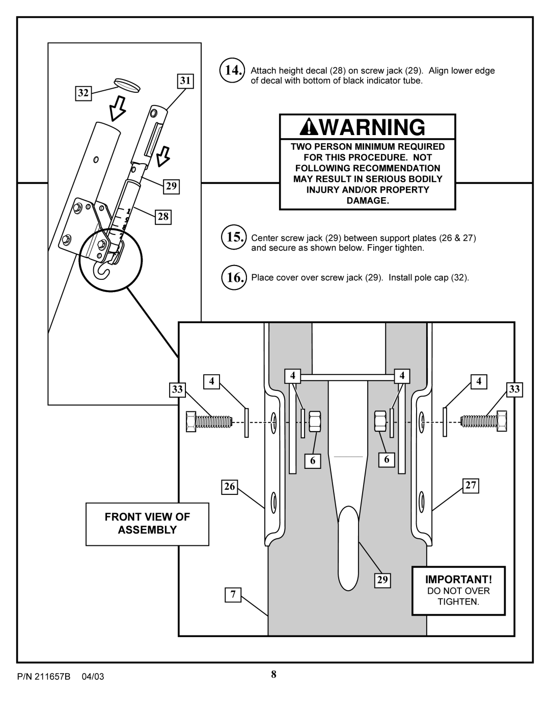
14. Attach height decal (28) on screw jack (29). Align lower edge of decal with bottom of black indicator tube.
![]() WARNING
WARNING
TWO PERSON MINIMUM REQUIRED
FOR THIS PROCEDURE. NOT
FOLLOWING RECOMMENDATION
MAY RESULT IN SERIOUS BODILY
INJURY AND/OR PROPERTY
DAMAGE.
15. Center screw jack (29) between support plates (26 & 27) and secure as shown below. Finger tighten.
16. Place cover over screw jack (29). Install pole cap (32).
|
| 4 | 4 |
| 4 | 4 |
|
|
|
|
| ||
|
| 33 |
|
|
| 33 |
|
|
| 6 | 6 |
|
|
|
|
| 26 |
|
| 27 |
|
| FRONT VIEW OF |
|
|
|
|
|
| ASSEMBLY |
|
|
|
|
|
|
|
| 29 |
| IMPORTANT! |
|
|
| 7 |
|
| DO NOT OVER |
|
|
|
|
| TIGHTEN. | |
|
|
|
|
|
| |
P/N 211657B | 04/03 |
| 8 |
|
|
|
