Connecting the Set-Top Box
 Front & Real Panel


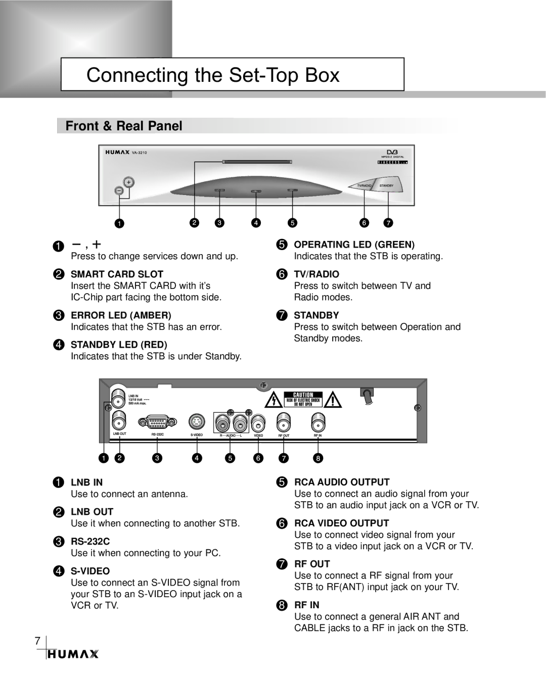
1, ![]()
Press to change services down and up.
2SMART CARD SLOT
5OPERATING LED (GREEN) Indicates that the STB is operating.
6TV/RADIO
| Insert the SMART CARD with it’s | Press to switch between TV and |
| Radio modes. | |
3 | ERROR LED (AMBER) | 7 STANDBY |
| Indicates that the STB has an error. | Press to switch between Operation and |
4 | STANDBY LED (RED) | Standby modes. |
|
Indicates that the STB is under Standby.
1LNB IN
Use to connect an antenna.
2LNB OUT
Use it when connecting to another STB.
3
Use it when connecting to your PC.
5RCA AUDIO OUTPUT
Use to connect an audio signal from your STB to an audio input jack on a VCR or TV.
6RCA VIDEO OUTPUT
Use to connect video signal from your STB to a video input jack on a VCR or TV.
4 | 7 | RF OUT |
| Use to connect a RF signal from your | |
Use to connect an |
| |
| STB to RF(ANT) input jack on your TV. | |
your STB to an |
| |
8 |
| |
VCR or TV. | RF IN | |
|
| Use to connect a general AIR ANT and |
|
| CABLE jacks to a RF in jack on the STB. |
7
