USER INTERFACE
The LEGEND 3000 User Interface is made up of the following components: knobs and the LCD Display, which in turn is made up of the RTS and the Chart Windows.
Knobs
Four knobs on the LEGEND 3000 SERIES control all user settings: MODE, GAIN, CONTROL PANEL and RANGE.
Mode Knob
The MODE knob selects how the LEGEND 3000 SERIES locates the bottom and graphs the information on the display. Turn the knob until the pointer aligns with the desired mode of operation. See Modes of Operation for more information.
Gain Knob
The GAIN knob controls the gain (sometimes called sensitivity) of the sonar receiver. Gain also powers the unit on or off. When the LEGEND 3000 SERIES is off, press Gain to turn the unit on. Press and hold Gain to turn the unit off. Turn the Gain knob clockwise to increase the gain; turn counterclockwise to decrease the gain. As you turn the knob, only new sonar information being graphed shows the effect of the gain change.
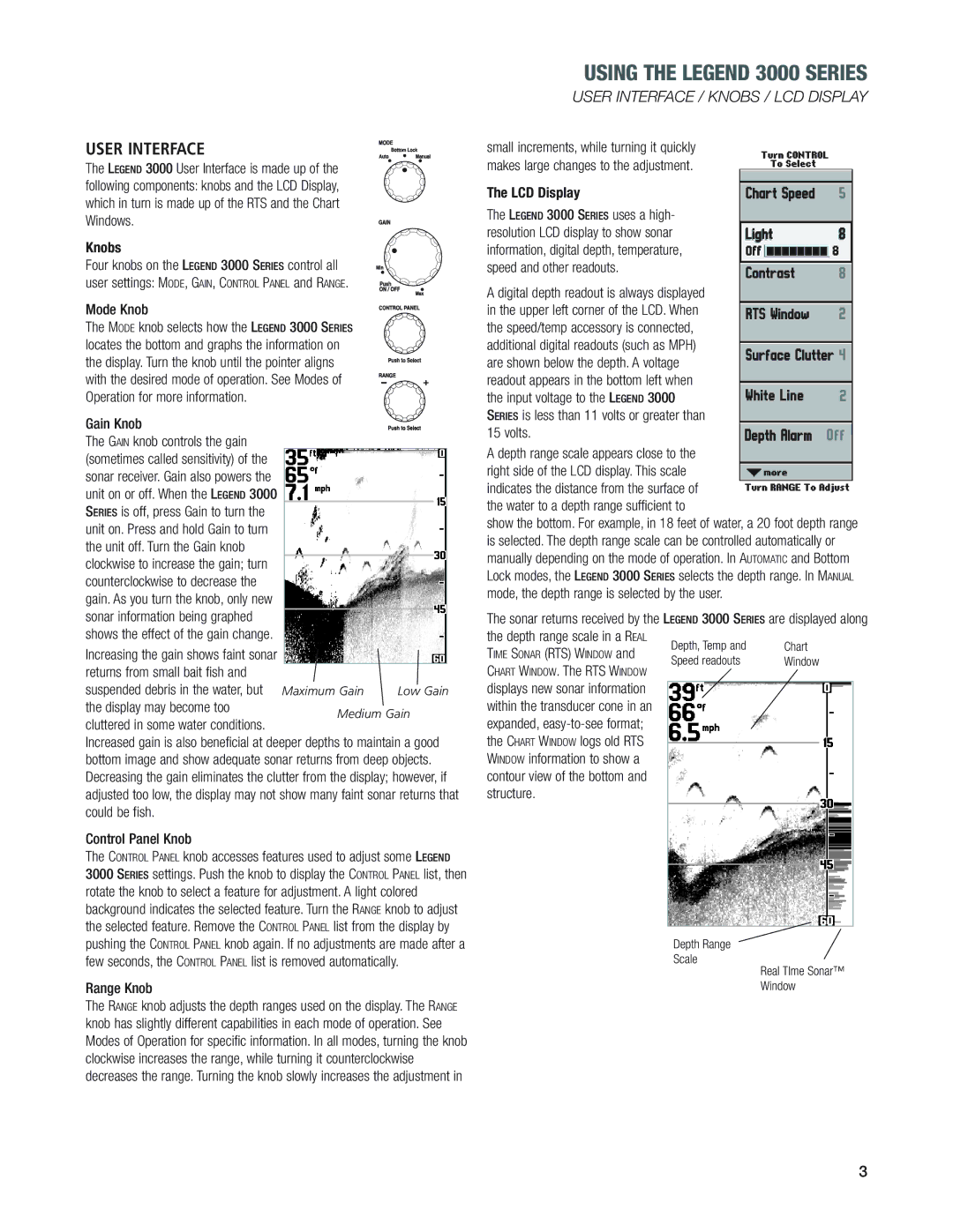
Increasing the gain shows faint sonar returns from small bait fish and
suspended debris in the water, but Maximum Gain Low Gain the display may become too
cluttered in some water conditions.
Increased gain is also beneficial at deeper depths to maintain a good bottom image and show adequate sonar returns from deep objects. Decreasing the gain eliminates the clutter from the display; however, if adjusted too low, the display may not show many faint sonar returns that could be fish.
Control Panel Knob
The CONTROL PANEL knob accesses features used to adjust some LEGEND 3000 SERIES settings. Push the knob to display the CONTROL PANEL list, then rotate the knob to select a feature for adjustment. A light colored background indicates the selected feature. Turn the RANGE knob to adjust the selected feature. Remove the CONTROL PANEL list from the display by pushing the CONTROL PANEL knob again. If no adjustments are made after a few seconds, the CONTROL PANEL list is removed automatically.
Range Knob
The RANGE knob adjusts the depth ranges used on the display. The RANGE knob has slightly different capabilities in each mode of operation. See Modes of Operation for specific information. In all modes, turning the knob clockwise increases the range, while turning it counterclockwise decreases the range. Turning the knob slowly increases the adjustment in