
41597-01 specifications
The Hunter Fan 41597-01 is a remarkable ceiling fan that blends traditional style with modern technology, making it an ideal choice for enhancing both aesthetics and comfort in your home. With a sleek design and a range of impressive features, this ceiling fan is perfect for any room, from cozy living spaces to larger areas.One of the key characteristics of the Hunter Fan 41597-01 is its elegant finish, typically available in rich wood tones or contemporary metallic options. This versatility allows it to complement various interior design themes, from rustic to modern. The fan's blades are engineered for optimal airflow, ensuring effective circulation while maintaining a quiet operation, which is essential for a peaceful home environment.
The Hunter Fan 41597-01 comes equipped with WhisperWind motor technology. This innovative feature guarantees powerful airflow without the distracting noise often associated with conventional ceiling fans. This makes the fan ideal for bedrooms or spaces where tranquility is a priority, allowing you to enjoy a comfortable climate without disruption.
Another standout feature is the fan's energy efficiency. Equipped with LED light kits, it provides illumination while consuming less power compared to traditional bulbs. This not only contributes to lower energy bills but also aligns with eco-friendly initiatives, making it a responsible choice for energy-conscious homeowners.
In addition to its aesthetic appeal and energy efficiency, the Hunter Fan 41597-01 offers versatile speed settings. With multiple speeds to choose from, you can customize airflow according to your needs, whether you need a gentle breeze or a stronger draft during warmer months. The fan's reversible motor also allows for year-round use; during summer, it can create a cooling downdraft, while in winter, it can be reversed to circulate warm air trapped at the ceiling level.
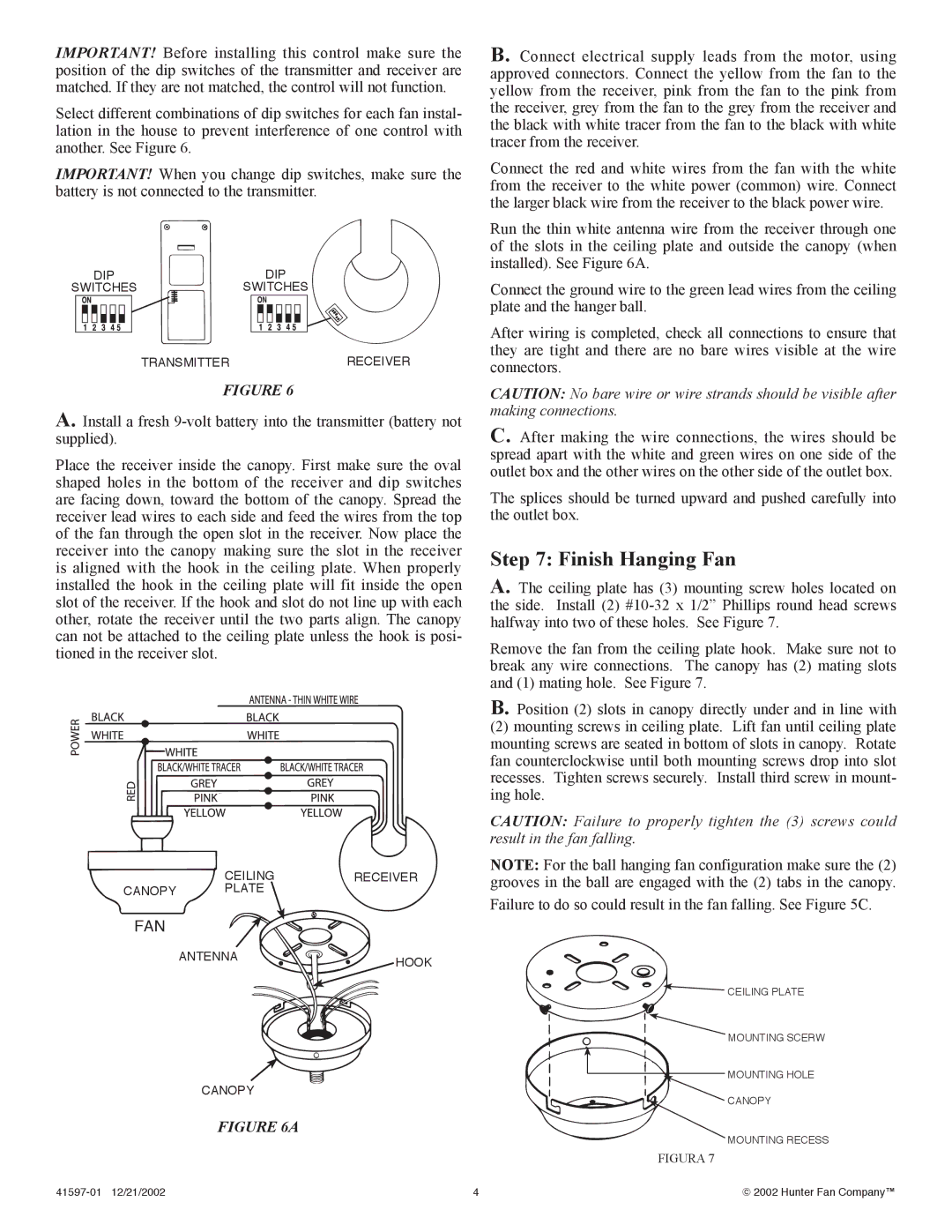
Installation is made easy with the fan's user-friendly mounting system, which accommodates various ceiling heights. This adaptability ensures that the Hunter Fan 41597-01 can be installed in almost any room without complications.
The Hunter Fan 41597-01 also often includes smart home compatibility, allowing you to control it remotely via smartphone or voice commands when paired with compatible systems. This feature adds an extra layer of convenience, making it easier than ever to maintain your desired comfort levels throughout the day.
In summary, the Hunter Fan 41597-01 stands out due to its sophisticated design, advanced motor technology, energy efficiency, adjustable speed settings, easy installation, and connectivity options. It's a perfect blend of style and functionality, making it a worthy addition to any home.