5
4.Align the slotted holes (refer to Figure 9) in the ceiling plate with the pilot holes in the wood support structure. Note: The isolation pads should be flush against the ceiling.
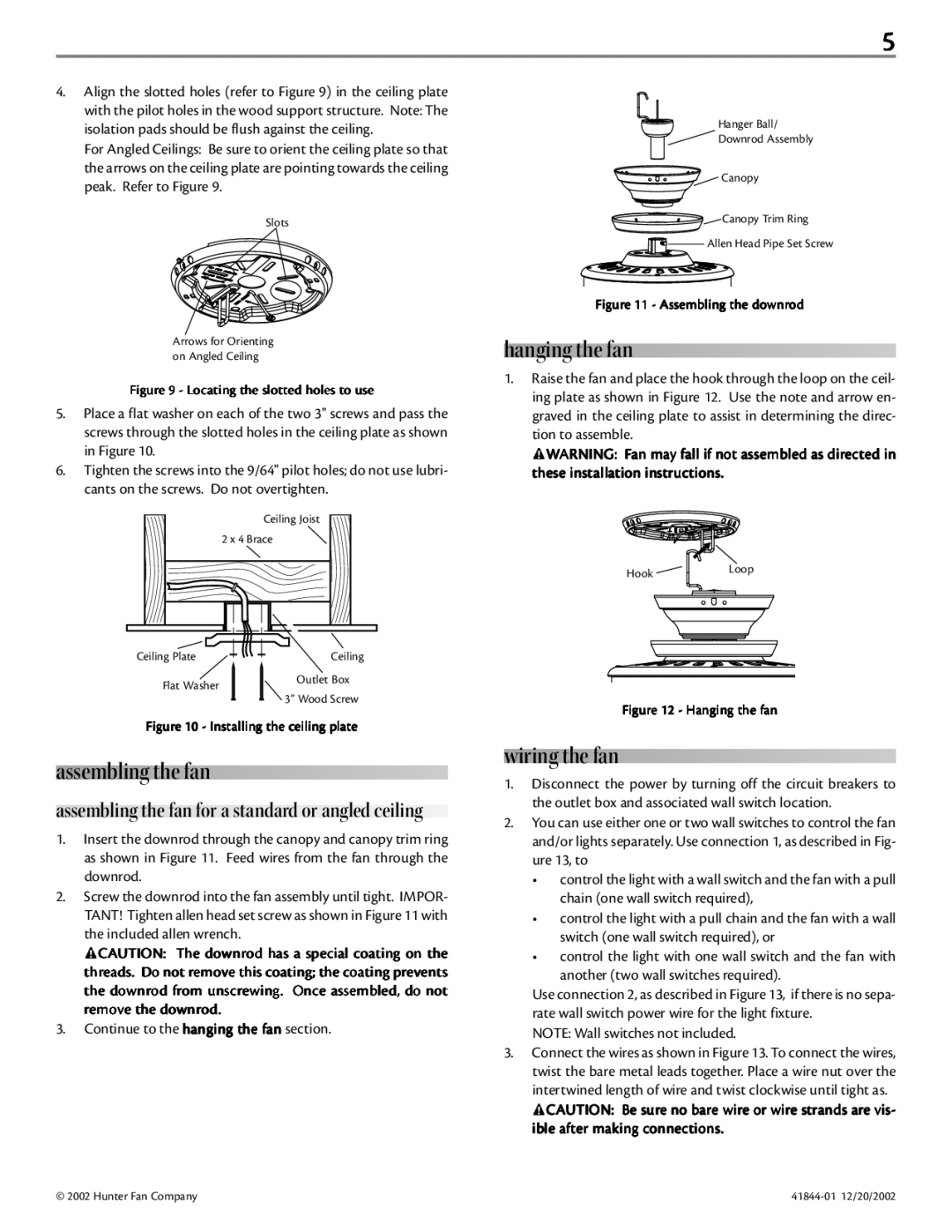
For Angled Ceilings: Be sure to orient the ceiling plate so that the arrows on the ceiling plate are pointing towards the ceiling peak. Refer to Figure 9.
Slots
Arrows for Orienting on Angled Ceiling
Figure 9 - Locating the slotted holes to use
5.Place a flat washer on each of the two 3" screws and pass the screws through the slotted holes in the ceiling plate as shown in Figure 10.
6.Tighten the screws into the 9/64" pilot holes; do not use lubri- cants on the screws. Do not overtighten.
Ceiling Joist
2 x 4 Brace
Ceiling Plate | Ceiling | |
Flat Washer | Outlet Box | |
3” Wood Screw | ||
|
Figure 10 - Installing the ceiling plate
assembling the fan
assembling the fan for a standard or angled ceiling
1.Insert the downrod through the canopy and canopy trim ring as shown in Figure 11. Feed wires from the fan through the downrod.
2.Screw the downrod into the fan assembly until tight. IMPOR- TANT! Tighten allen head set screw as shown in Figure 11 with the included allen wrench.
![]() CAUTION: The downrod has a special coating on the threads. Do not remove this coating; the coating prevents the downrod from unscrewing. Once assembled, do not remove the downrod.
CAUTION: The downrod has a special coating on the threads. Do not remove this coating; the coating prevents the downrod from unscrewing. Once assembled, do not remove the downrod.
3.Continue to the hanging the fan section.
Hanger Ball/
Downrod Assembly
Canopy
Canopy Trim Ring
Allen Head Pipe Set Screw
Figure 11 - Assembling the downrod
hanging the fan
1.Raise the fan and place the hook through the loop on the ceil- ing plate as shown in Figure 12. Use the note and arrow en- graved in the ceiling plate to assist in determining the direc- tion to assemble.
![]() WARNING: Fan may fall if not assembled as directed in these installation instructions.
WARNING: Fan may fall if not assembled as directed in these installation instructions.
HookLoop
Figure 12 - Hanging the fan
wiring the fan
1.Disconnect the power by turning off the circuit breakers to the outlet box and associated wall switch location.
2.You can use either one or two wall switches to control the fan and/or lights separately. Use connection 1, as described in Fig- ure 13, to
•control the light with a wall switch and the fan with a pull chain (one wall switch required),
•control the light with a pull chain and the fan with a wall switch (one wall switch required), or
•control the light with one wall switch and the fan with another (two wall switches required).
Use connection 2, as described in Figure 13, if there is no sepa- rate wall switch power wire for the light fixture.
NOTE: Wall switches not included.
3.Connect the wires as shown in Figure 13. To connect the wires, twist the bare metal leads together. Place a wire nut over the intertwined length of wire and twist clockwise until tight as.
![]() CAUTION: Be sure no bare wire or wire strands are vis- ible after making connections.
CAUTION: Be sure no bare wire or wire strands are vis- ible after making connections.
© 2002 Hunter Fan Company |