8
3.Align the keyhole slots in the upper switch housing with the housing assembly screws installed previously.
4.Turn the upper switch housing counterclockwise until the housing assembly screws are firmly situated in the narrow end of the keyhole slots as shown in Figure 23. Install the one re- maining
Figure 23 - Mounting the upper switch housing
![]() CAUTION: Make sure the upper switch housing is se- curely attached to the switch housing mounting plate. Fail- ure to properly attach and tighten all three housing as- sembly screws could result in the switch housing and light fixture falling.
CAUTION: Make sure the upper switch housing is se- curely attached to the switch housing mounting plate. Fail- ure to properly attach and tighten all three housing as- sembly screws could result in the switch housing and light fixture falling.
attaching the lower switch housing
1.Connect the upper plug connector from the motor to the lower plug connector in the lower switch housing assembly. See Fig- ure 24.
NOTE: Both plug connectors are polarized and will only fit to- gether one way. Make sure that both connectors are properly aligned before connecting them together. Incorrect connec- tion could cause improper operation and damage to the prod- uct.
operating your ceiling fan
1.Turn on electrical power to the fan.
2.The fan pull chain controls power to the fan. The pull chain has four settings in sequence: High, Medium, Low and Off.
•Pull the chain slowly to change settings.
•Release slowly to prevent the chain from recoiling into the blades.
•The chain uses a breakaway connector that separates if the chain is jerked. If this happens, simply reinsert the chain into the connector.
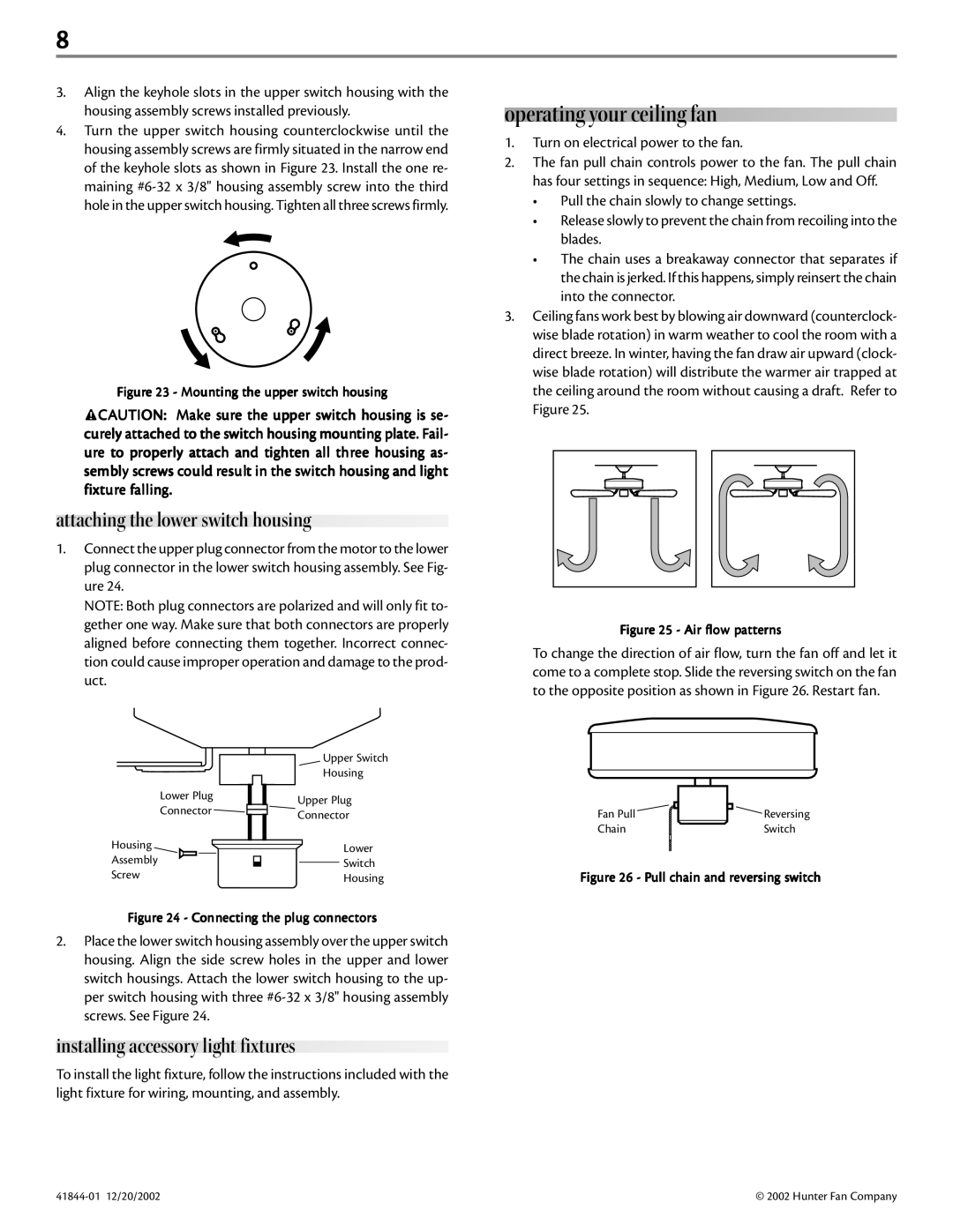
3.Ceiling fans work best by blowing air downward (counterclock- wise blade rotation) in warm weather to cool the room with a direct breeze. In winter, having the fan draw air upward (clock- wise blade rotation) will distribute the warmer air trapped at the ceiling around the room without causing a draft. Refer to Figure 25.
Figure 25 - Air flow patterns
To change the direction of air flow, turn the fan off and let it come to a complete stop. Slide the reversing switch on the fan to the opposite position as shown in Figure 26. Restart fan.
Lower Plug
Connector
Housing
Assembly
Screw
Upper Switch
Housing
Upper Plug
Connector
Lower
Switch
Housing
Fan Pull![]() Reversing
Reversing
ChainSwitch
Figure 26 - Pull chain and reversing switch
Figure 24 - Connecting the plug connectors
2.Place the lower switch housing assembly over the upper switch housing. Align the side screw holes in the upper and lower switch housings. Attach the lower switch housing to the up- per switch housing with three
installing accessory light fixtures
To install the light fixture, follow the instructions included with the light fixture for wiring, mounting, and assembly.
© 2002 Hunter Fan Company |