4 •Wiring the Fan | Wiring | |
codes and ANSI/NFPA 70. If you are unfamiliar with wiring, use a | ||
All wiring must be in accordance with national and local electrical |
| |
qualified electrician. | & | |
Bracket | ||
Wall switches are not included. Select an acceptable |
| |
in accordance with national and local electrical codes. | Install | |
| ||
a wire nut over them, then twist clockwise until tight. For all these |
| |
connections use the wire connectors provided. |
| |
| ||
ceiling to the green ground wire (grounded) from the ceiling plate |
| |
and the green ground wire from the fan. |
| |
| ||
white wire (ungrounded) from the fan. |
| |
Wire | ||
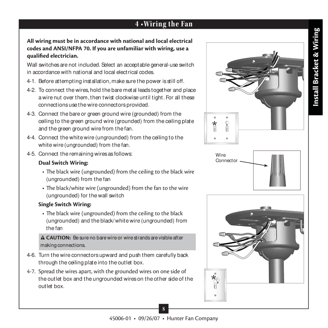
Dual Switch Wiring: | Connector | |
|
•The black wire (ungrounded) from the ceiling to the black wire
(ungrounded) from the fan
•The black/white wire (ungrounded) from the fan to the wire
(ungrounded) for the wall switch
Single Switch Wiring:
•The black wire (ungrounded) from the ceiling to the black
(ungrounded) and the black/white wire (ungrounded) from the fan
![]() CAUTION: Be sure no bare wire or wire strands are visible after making connections.
CAUTION: Be sure no bare wire or wire strands are visible after making connections.
8