7 • Completing Your Installation With or Without a Bowl Light Fixture (Continued)
| ||
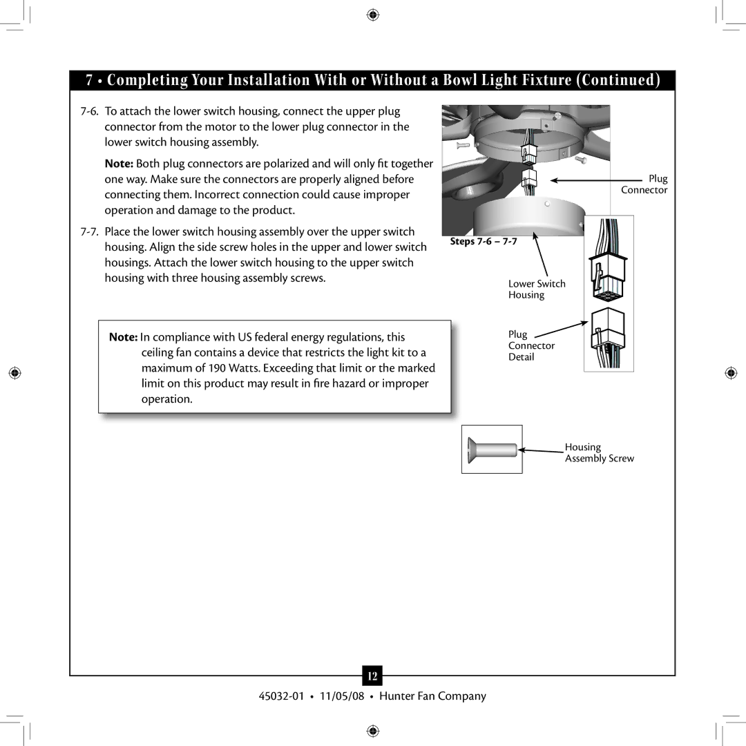
connector from the motor to the lower plug connector in the |
| |
lower switch housing assembly. |
| |
Note: Both plug connectors are polarized and will only fit together |
| |
one way. Make sure the connectors are properly aligned before | Plug | |
connecting them. Incorrect connection could cause improper | Connector | |
| ||
operation and damage to the product. |
| |
Steps | ||
housing. Align the side screw holes in the upper and lower switch | ||
| ||
housings. Attach the lower switch housing to the upper switch |
| |
housing with three housing assembly screws. | Lower Switch | |
| ||
| Housing | |
Note: In compliance with US federal energy regulations, this | Plug | |
ceiling fan contains a device that restricts the light kit to a | Connector | |
Detail | ||
maximum of 190 Watts. Exceeding that limit or the marked | ||
| ||
limit on this product may result in fire hazard or improper |
| |
operation. |
| |
| Housing | |
| Assembly Screw |
12