3.2THE POWER INVERTER OUTPUT WAVEFORM
The AC output waveform of the POWER INVERTER is known as “modified sine wave”. It is a waveform that has characteristics similar to the sine wave shape of utility power. This type of waveform is suitable for most AC loads, including linear and switching power supplies used in electronic equipment, transformers, and motors.
The modified sine wave produced by the POWER INVERTER has an RMS (root mean square) voltage of 110 volts, which is the same as standard household power. Most AC voltmeters (both digital and analog) are sensitive to the average value of the waveform rather than the RMS value. They are calibrated for RMS voltage under the assumption that the waveform measured will be a pure sine wave. These meters will not read the RMS voltage of a modified sine wave correctly. They will read about 20 to 30 volts low when measuring the output of the inverter. For accurate measurement of the output voltage of this unit, use a true RMS reading voltmeter such as a Fluke 87, Fluke 8060A, Fluke 77/99 series, Beckman 4410, or Triplett 4200.
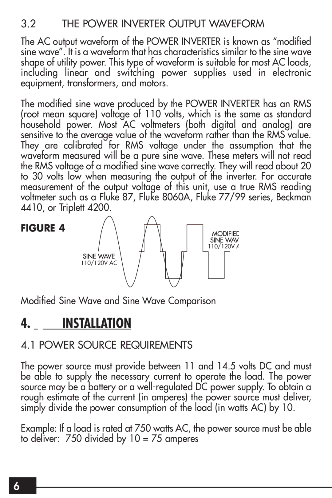
FIGURE 4
110/120V A
110/120V AC
Modified Sine Wave and Sine Wave Comparison
4.INSTALLATION
4.1 POWER SOURCE REQUIREMENTS
The power source must provide between 11 and 14.5 volts DC and must be able to supply the necessary current to operate the load. The power source may be a battery or a
Example: If a load is rated at 750 watts AC, the power source must be able
to deliver: 750 divided by 10 = 75 amperes
6
6