SETUP AND ADJUSTMENTS
Mower Deck Leveling | Loosen the nuts directly behind each ball joint on | |
Position machine on a flat surface. Preferably level | both rods that connect the pump arm to the mo- | |
concrete. | tion control assemblies. FIG - 5 | |
Check the tire pressure in all four tires. Inflation | Start the engine. The park brake must be engaged | |
should be 15 psi. | and the motion control levers in the neutral slots | |
Place 2x4’s on edge under the cutting deck from | to start the engine. Run the engine approximately | |
half throttle | ||
front to rear and lower the deck down onto 2x4’s. | ||
| ||
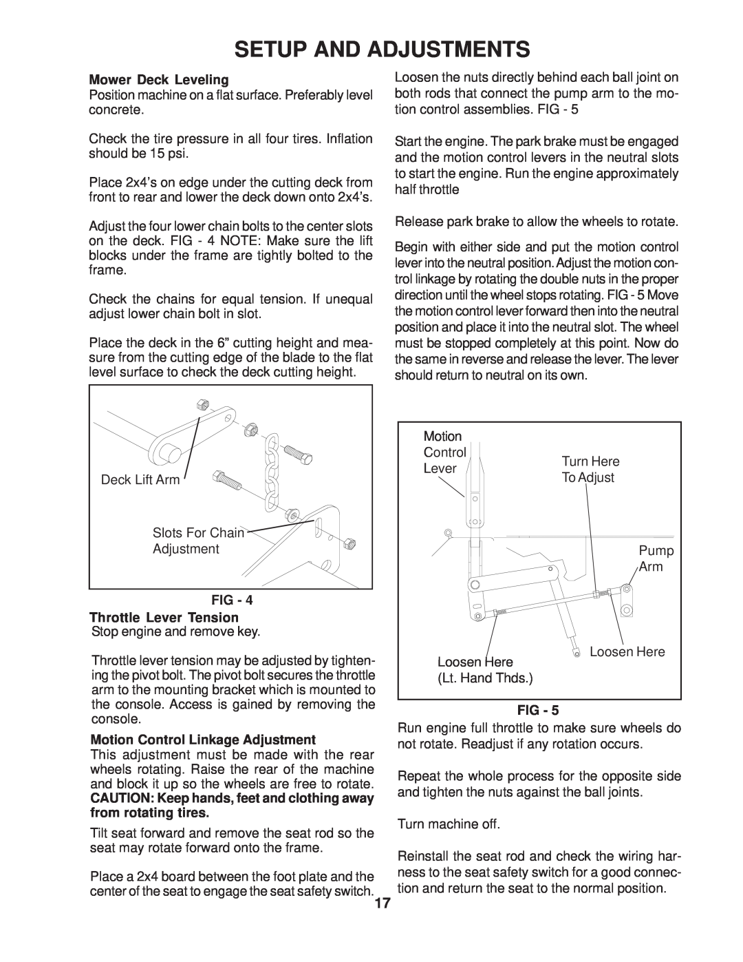
Adjust the four lower chain bolts to the center slots | Release park brake to allow the wheels to rotate. | |
on the deck. FIG - 4 NOTE: Make sure the lift | Begin with either side and put the motion control | |
blocks under the frame are tightly bolted to the | ||
lever into the neutral position.Adjust the motion con- | ||
frame. | ||
trol linkage by rotating the double nuts in the proper | ||
| ||
Check the chains for equal tension. If unequal | direction until the wheel stops rotating. FIG - 5 Move | |
adjust lower chain bolt in slot. | the motion control lever forward then into the neutral | |
Place the deck in the 6” cutting height and mea- | position and place it into the neutral slot. The wheel | |
must be stopped completely at this point. Now do | ||
sure from the cutting edge of the blade to the flat | the same in reverse and release the lever. The lever | |
level surface to check the deck cutting height. | should return to neutral on its own. |
| Motion |
| |
| Control | Turn Here | |
| Lever | ||
Deck Lift Arm | To Adjust | ||
| |||
Slots For Chain |
|
| |
Adjustment |
| Pump | |
|
| Arm | |
FIG - 4 |
|
| |
Throttle Lever Tension |
|
| |
Stop engine and remove key. |
|
| |
Throttle lever tension may be adjusted by tighten- | Loosen Here | Loosen Here | |
| |||
ing the pivot bolt. The pivot bolt secures the throttle | (Lt. Hand Thds.) |
| |
arm to the mounting bracket which is mounted to |
|
| |
the console. Access is gained by removing the | FIG - 5 |
| |
console. |
| ||
Run engine full throttle to make sure wheels do | |||
Motion Control Linkage Adjustment | |||
not rotate. Readjust if any rotation occurs. | |||
This adjustment must be made with the rear |
|
| |
wheels rotating. Raise the rear of the machine | Repeat the whole process for the opposite side | ||
and block it up so the wheels are free to rotate. | |||
and tighten the nuts against the ball joints. | |||
CAUTION: Keep hands, feet and clothing away | |||
|
| ||
from rotating tires. | Turn machine off. |
| |
Tilt seat forward and remove the seat rod so the |
| ||
|
| ||
seat may rotate forward onto the frame. | Reinstall the seat rod and check the wiring har- | ||
| |||
Place a 2x4 board between the foot plate and the | ness to the seat safety switch for a good connec- | ||
center of the seat to engage the seat safety switch.17 | tion and return the seat to the normal position. | ||
|
| ||