temperature. If the coolant reaches an unsafe level during operation, shut down the machine as soon as possible. Never risk continued operation when the gauge needle is in the high range; high temperatures can severely damage the engine.
Never risk continued operation when light remains on: high temperatures can severely damage the engine.
An audible alarm will sound when the engine coolant is close to overheating.
I.Alternator warning light (Fig. 3-1) — this light comes on when the ignition switch is placed in the RUN position and stays lit until the engine is running and the battery is being charged. If light comes on during operation, shut engine off immediately, locate and correct the problem.
If light remains on while engine is running, it indicates that the battery is being discharged.
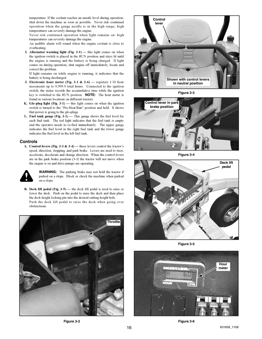
J.Electronic hour meter (Fig. 3-1 & 3-6) — registers 1/10 hour increments up to 9,999.9 total hours. Connected to the ignition switch, the meter records the accumulative time while the ignition key is switched to the RUN position. NOTE: The hour meter is found in various locations on different tractors.
K.Glo-plug light (Fig. 3-1) — this light comes on when the ignition switch is turned to the “Pre-Heat/Run” position and held. It shows that power is going to the glo-plugs.
L.Fuel tank gauge (Fig. 3-1) — This gauge shows the fuel level for each fuel tank. The red light indicates that the fuel tank is empty and the operator needs to re-fuel immediately. The upper gauge indicates the fuel level in the right fuel tank and the lower gauge indicates the fuel level in the left fuel tank.
Controls
A.Control levers (Fig. 3-3 & 3-4) — these levers control the tractor’s speed, direction, stopping, and park brake. Levers are used to steer, accelerate, decelerate and change direction. When the control levers are in the park brake position (3-3) the tractor will not move when the engine is on and drive pumps are operating.
WARNING: The parking brake may not hold the tractor if parked on a slope. Block or chock the machine when parked on a slope.
B.Deck lift pedal (Fig. 3-5) — the deck lift pedal is used to raise or lower the deck. Push on the pedal to raise the deck and then place the deck height locking pin into the desired cutting height hole.
Push the deck lift pedal to raise the deck when going over obstructions.
Throttle
Figure 3-2

