corresponding side and turn the stop (set screw) inward to stop the control levers slightly before the pump bottoms out. Lock in place when the adjustment is correct by
3. Do this for each side.
To adjust the stops for driving straight when control levers are against the stops during operation:
1.Determine which drive tire is rotating too fast when both control levers are against the stops. Then stop the tractor and loosen the lock nut on the side which is rotating too fast and turn the stop (set screw) inward to stop the control lever sooner. Tighten the lock nut on the stop and test again. Repeat this procedure until unit drives straight.
NOTE: Since this is a hydrostatic drive, variables such as temperature of oil, efficiency of pumps and motors, tire pressure etc. may effect the con- sistency of the ability to rely on the stops to drive straight without the operator making minor steering adjustments with the control arms.
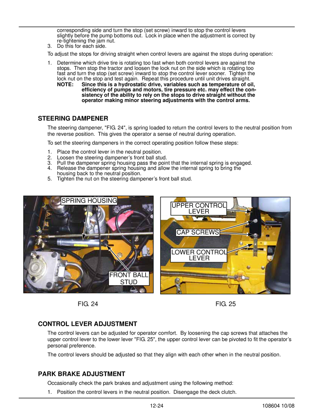
STEERING DAMPENER
The steering dampener, "FIG. 24", is spring loaded to return the control levers to the neutral position from the reverse position. This gives the operator a sense of neutral during operation.
To set the steering dampeners in the correct operating position follow these steps:
1.Place the control lever in the neutral position.
2.Loosen the steering dampener’s front ball stud.
3.Pull the dampener spring housing pass the point that the internal spring is engaged.
4.Release the dampener spring housing and allow the internal spring to bring the housing back to the neutral position.
5.Tighten the nut on the steering dampener’s front ball stud.
SPRING HOUSING
FRONT BALL
STUD
UPPER CONTROL LEVER ![]()
![]()
CAP SCREWS![]()
LOWER CONTROL
LEVER
FIG. 24 | FIG. 25 |
CONTROL LEVER ADJUSTMENT
The control levers can be adjusted for operator comfort. By loosening the cap screws that attaches the upper control lever to the lower lever "FIG. 25", the upper control lever can be pivoted to fit the operator’s personal preference.
The control levers should be adjusted so that they align with each other when in the neutral position.
PARK BRAKE ADJUSTMENT
Occasionally check the park brakes and adjustment using the following method: 1. Position the control levers in the neutral position. Disengage the deck clutch.
108604 10/08 |