TOOLS REQUIRED
Removal
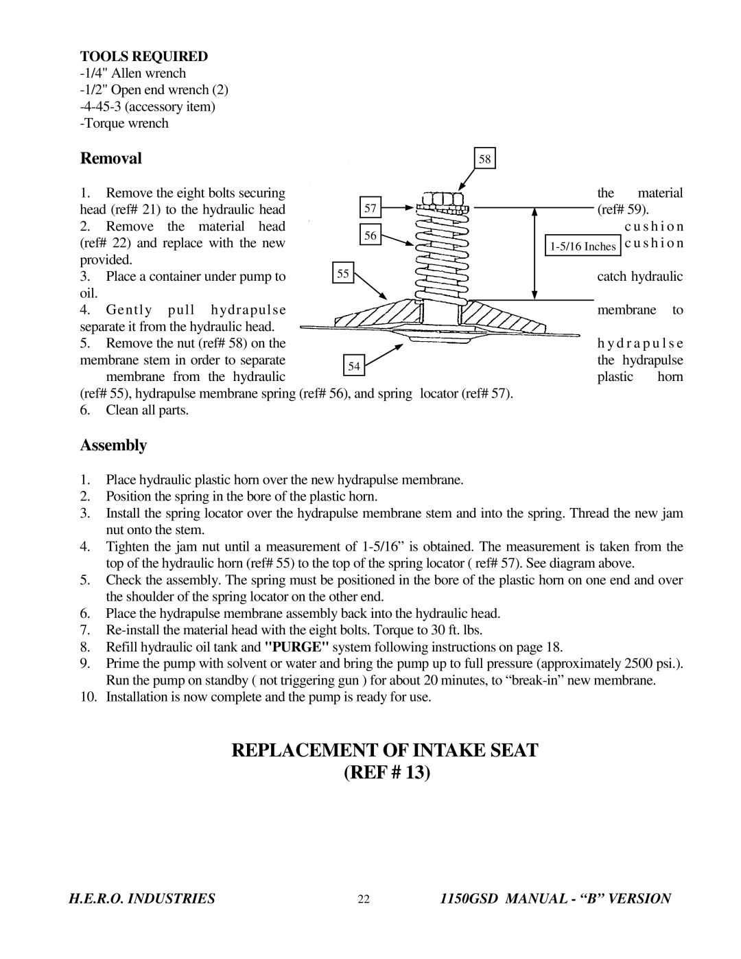
58 |
1. | Remove the eight bolts securing |
|
|
|
|
|
|
|
|
|
|
|
| the | material | |||
head (ref# 21) to the hydraulic head |
| 57 |
|
|
|
|
|
|
| (ref# 59). |
| |||||||
|
|
|
|
|
|
| ||||||||||||
2. | Remove | the | material head |
|
|
|
|
|
|
|
|
|
|
|
|
| c u s h i o n | |
|
|
| 56 |
|
|
|
|
|
|
|
| |||||||
(ref# 22) and replace with the new |
|
|
|
|
|
|
| c u s h i o n | ||||||||||
|
|
|
|
|
|
|
|
|
|
| ||||||||
provided. |
|
|
|
|
|
|
|
|
|
|
|
|
|
|
|
|
| |
|
|
|
|
|
|
|
|
|
|
|
|
|
|
|
|
| ||
3. | Place a container under pump to | 55 |
|
|
|
|
|
|
|
|
|
| catch hydraulic | |||||
oil. |
|
|
|
|
|
|
|
|
|
|
|
|
|
|
|
|
|
|
|
|
|
|
|
|
|
|
|
|
|
|
|
|
|
|
|
| |
4. | Gently | pull | hydrapulse |
|
|
|
|
|
|
|
|
|
|
|
| membrane | to | |
separate it from the hydraulic head. |
|
|
|
|
|
|
|
|
|
|
|
|
|
|
| |||
5. | Remove the nut (ref# 58) on the |
|
|
|
|
|
|
|
|
|
|
|
| h y d r a p u l s e | ||||
membrane stem in order to separate |
|
|
|
|
|
|
|
|
|
|
|
| the | hydrapulse | ||||
| 54 |
|
|
|
|
|
|
|
|
| ||||||||
| membrane | from the hydraulic |
|
|
|
|
|
|
|
|
|
| plastic | horn | ||||
|
|
|
|
|
|
|
|
|
|
|
|
| ||||||
(ref# 55), hydrapulse membrane spring (ref# 56), and spring | locator (ref# 57). |
|
| |||||||||||||||
6.Clean all parts.
Assembly
1.Place hydraulic plastic horn over the new hydrapulse membrane.
2.Position the spring in the bore of the plastic horn.
3.Install the spring locator over the hydrapulse membrane stem and into the spring. Thread the new jam nut onto the stem.
4.Tighten the jam nut until a measurement of
5.Check the assembly. The spring must be positioned in the bore of the plastic horn on one end and over the shoulder of the spring locator on the other end.
6.Place the hydrapulse membrane assembly back into the hydraulic head.
7.
8.Refill hydraulic oil tank and "PURGE" system following instructions on page 18.
9.Prime the pump with solvent or water and bring the pump up to full pressure (approximately 2500 psi.). Run the pump on standby ( not triggering gun ) for about 20 minutes, to
10.Installation is now complete and the pump is ready for use.
REPLACEMENT OF INTAKE SEAT
(REF # 13)
H.E.R.O. INDUSTRIES | 22 | 1150GSD MANUAL - “B” VERSION |