ThinkCentre
Page
ThinkCentre
Fourth Edition July
Contents
Related service
Important Safety Information
About this manual
Hardware Maintenance Manual
Features
General information
Input/output features
Physical specifications
IBM preinstalled software
Type
Height 140 mm 5.5 Width 425 mm 16.7 Depth 425 mm 16.7
Types 2296
Types 8198
Hardware Maintenance Manual
General Checkout
Set Power-On Self-Test to Enhanced
Did YOU Receive the Correct RESPONSE?
General Checkout
Hardware Maintenance Manual
Navigating through the diagnostics programs
Diagnostics program download
Running diagnostics tests
Test results
Test selection
Fixed disk advanced test Fdat
Fixed-Disk Tests
Quick and Full erase hard drive
Viewing the test log
Hardware Maintenance Manual
Starting the IBM Setup Utility program
Viewing and changing settings
User password
Exiting from the IBM Setup Utility program
Using passwords
Administrator password
Selecting a temporary startup device
Using Security Profile by Device
Selecting a startup device
Changing the startup device sequence
Hardware Maintenance Manual
Locating connectors on the front Types 2296
Replacing FRUs
Type
Replacing FRUs
�1�USB connector �2�USB connector
Locating the connectors on the rear Types 2296
Type
Types 8198
Removing the cover
Type
Types 8198
Replacing FRUs
Locating components Types 2296
Type
Types 8198
�5�DIMM
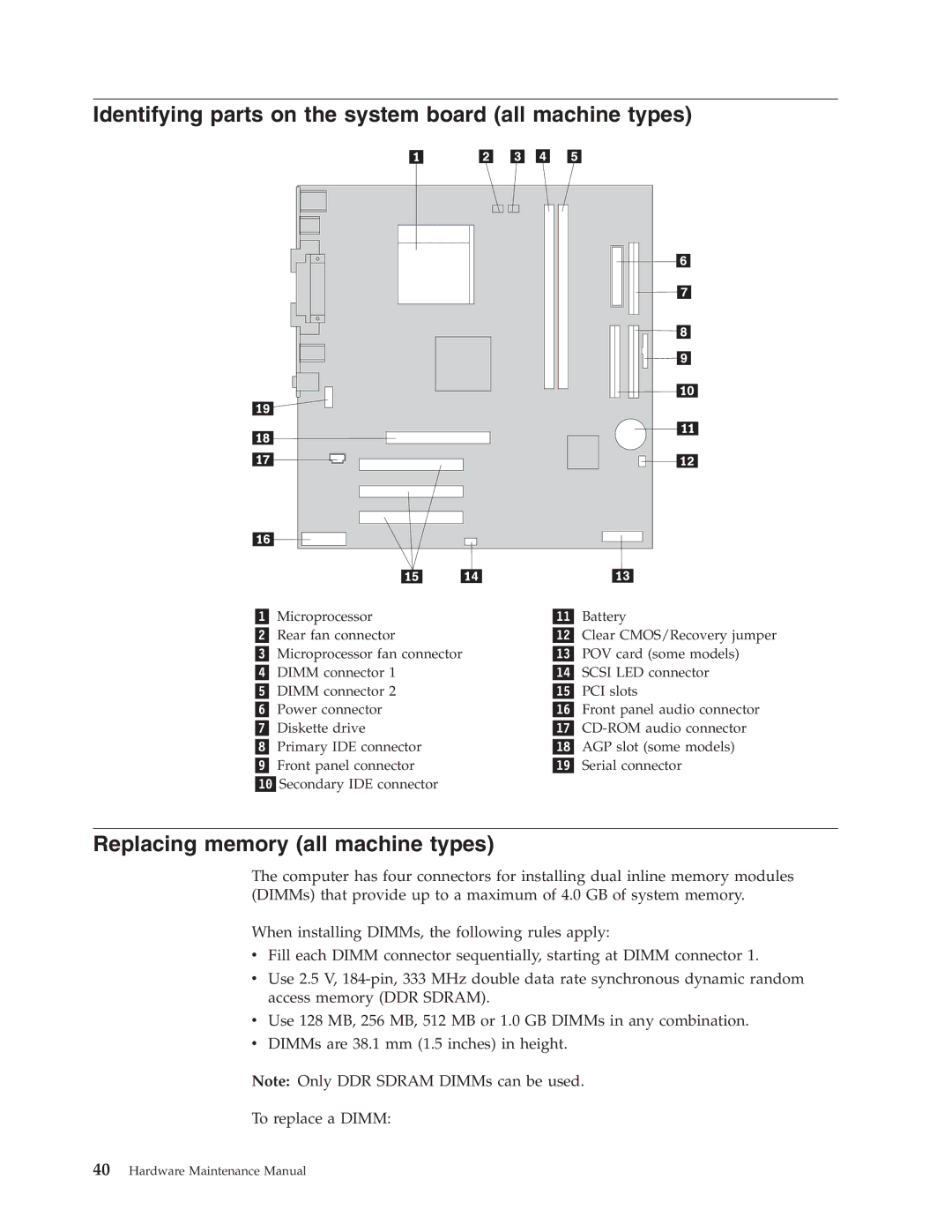
Identifying parts on the system board all machine types
Replacing memory all machine types
Replacing adapters Types 2296
Type
Types 8198
Hardware Maintenance Manual
Replacing internal drives
Drive bay information
Removing a drive
Installing a drive
Type
Removing a drive
Types 8198
Removing the drive
Installing a drive
Type
Installing a drive
Connecting the drive
Replacing the battery all machine types
Replacing the power supply Types 2296
Type
Types 8198
Type
Replacing a microprocessor all machine types
Microprocessor Thermal grease
Replacing the system board Types 2296, 8198, 8199,
Replacing the cover and connecting the cables Types 2296
Type
Types 8198
Type
Hardware Maintenance Manual
Error FRU/Action
Hard disk drive boot error
Power Supply Errors
Check/Verify FRU/Action
Diagnostic error codes
000-199-XXX Go to Undetermined problems on
Out is connected and/or enabled
It is connected and/or enabled
001-027-XXX Run Setup
Hardware Maintenance Manual
Symptom-to-FRU Index
005-010-XXX Video card, if installed 005-011-XXX
Diagnostic Error Code FRU/Action 001-300-XXX System board
005-00X-XXX Video card, if installed
005-024-XXX Video card, if installed
005-199-XXX
005-2XX-XXX Video card, if installed 005-3XX-XXX
005-198-XXX If a component is called out, make sure
006-000-XXX No action
011-001-XXX Remove external serial device, if
Diagnostic Error Code FRU/Action 011-000-XXX No action
011-027-XXX Run Setup, enable port
Present
014-013-XXX System board 014-014-XXX
014-027-XXX Run Setup, enable port
014-002-XXX System board 014-003-XXX
014-015-XXX Wrap plug
018-0XX-XXX Riser card, if installed
015-034-XXX Reboot the system
015-040-XXX Run setup and check for conflicts
015-015-XXX Remove USB devices and re-test
018-197-XXX Make sure the component that is called
Diagnostic Error Code FRU/Action 018-195-XXX PCI card
018-196-XXX Press F3 to review the log file
018-198-XXX Make sure the component that is called
025-027-XXX IDE signal cable
Diagnostic Error Code FRU/Action 020-199-XXX
025-00X-XXX IDE signal cable 025-01X-XXX
025-02X-XXX IDE signal cable 025-03X-XXX
035-0XX-XXX RAID signal cable
030-027-XXX Scsi signal cable
030-03X-XXX Scsi signal cable 030-04X-XXX
030-195-XXX Information
035-197-XXX Make sure the component that is called
071-00X-XXX Run Setup 071-01X-XXX
071-04X-XXX Run Setup
035-198-XXX If a component is called out, make sure
071-25X-XXX Speakers
Diagnostic Error Code FRU/Action 071-199-XXX
086-040-XXX Run Setup
080-000-XXX No action
086-199-XXX
086-197-XXX
086-198-XXX
089-000-XXX No action
170-196-XXX Press F3 to review the log file
Diagnostic Error Code FRU/Action 170-195-XXX Information
170-250-XXX Power supply 170-251-XXX
170-197-XXX Make sure the component that is called
175-250-XXX Check fans 175-251-XXX
Diagnostic Error Code FRU/Action 175-199-XXX
185-278-XXX Assure Asset Security Enabled
185-000-XXX No action
Mouse error
Hi-Capacity Cartridge Drive error
Keyboard error
Joystick error
3-1 1st 64K RAM test failed
Beep symptoms
Beeps Description
2 1st 64K RAM parity test failed
Symptom-to-FRU Index
Symptom/Error FRU/Action
No-beep symptoms
See Undetermined problems on
Post error codes
162 Run Setup and verify Configuration
Post Error Code FRU/Action 111 Reseat adapters
161 Run Setup
164 Run Setup. Check System Summary
Not listed above
Video Adapter if installed
262 Run Setup. Check System Summary
Setup Utility program, on
604 Run Setup and verify diskette
6XX
Hardware Maintenance Manual
Symptom-to-FRU Index
Hardware Maintenance Manual
Symptom-to-FRU Index
Hardware Maintenance Manual
Symptom-to-FRU Index
16500 Tape Attachment
Post Error Code FRU/Action 14932 External Display
161XX FaxConcentrator Adapter 164XX MB Internal Tape Drive
16520 Streaming Tape Drive
Replace memory module shown
Post Error Code FRU/Action 20105 to Printer/Scanner Option
Rotary Switch Circuit Board
Graphic
Hardware Maintenance Manual
Symptom-to-FRU Index
Miscellaneous error messages
Printer
See Power Supply Errors on
If network administrator is using
Lccm Hybrid RPL, check startup
Undetermined problems
Security features
Passwords
Erasing a lost or forgotten password clearing Cmos
Vital product data
Bios levels
Updating flashing Bios from your operating system
Recovering from a POST/BIOS update failure
Advanced Power Management
Power management
Automatic configuration and power interface Acpi Bios
Automatic Hardware Power Management features
Automatic Power-On features
Product Recovery Program
Create Recovery/Repair Diskette Disk to Disk Solution Only
Hardware Maintenance Manual
Machine Type
Item # 2296 FRUs
Item # FRUs
FRUs listed in the following table are not illustrated
Power Cords
Windows XP Home Recovery CDs
Keyboards RAK III Lite
This section lists the replaceable FRUs for Machine Type
FRU# CRU
FRU# CRU
FRUs listed in the following table are not illustrated
Windows 2000 Recovery CDs
Windows XP Pro Recovery CDs
Keyboards Standard PS/2 Black
7BG D3G 7CG 7DG 7EG 7FG 7GG
Power Cords
Side cover assembly all models 59P8547
HDD, 40GB Eide
US/UK/AP/TH models 76G 71G
8198 Windows XP Home Recovery CDs
FR/CF models 76G 71G
Windows XP Pro Recovery CDs
Keyboards Standard PS/2 Black
Machine Type
Trim bezel/Label kit all models 49P1900
CQU E2S E2D E2Y 68S 68D 68Y F5U
FRUs listed in the following table are not illustrated
Windows XP Pro Recovery CDs
US English models 14M 24M 53M B3M 19K1910
Machine Type
FRU# CRU
JP model 11J
HK model 63B
Chassis assembly all models 74P2256
Chinese/US model 63B 19K1915 Power Cords
Power Cord model 11J 1838576 Power Cord model 63B 02K0545
Japanese model 11J 89P8320 Keyboards RAK III Lite
FRU# CRU
FRU# CRU
US models 54A 54H 54T 13R9673 SC model 54C
JP model 33J
Hardware Maintenance Manual
Safety information
General safety
Electrical safety
Safety inspection guide
Handling electrostatic discharge-sensitive devices
Grounding requirements
Safety notices multi-lingual translations
To Connect To Disconnect
Do not
Related service information
Perigo
Para Conectar Para Desconectar
Precaución
Fonte de energia elétrica
Related service information
Hardware Maintenance Manual
Related service information
Hardware Maintenance Manual
Related service information
Hardware Maintenance Manual
Related service information
Hardware Maintenance Manual
Connexion Déconnexion
Faites-vous aider pour soulever ce produit
Courant
Vorsicht
Kabel anschlieβen Kabel lösen
≥18 kg ≥32 kg ≥55 kg
Achtung
Pericolo
Per collegare Per scollegare
≥18 kg ≥32 kg ≥55 kg
Siano scollegati dalla sorgente di alimentazione
Hardware Maintenance Manual
Related service information
Hardware Maintenance Manual
Peligro
Para la conexin Para la desconexiín
Tome medidas de seguridad al levantar el producto
Precaución
Send us your comments
Problem determination tips
Trademarks
Page
Part Number 74P2662