3 CONTROL CABLE SIGNALS

Transceiver setting

IC-M700 with serial number 2500 and below

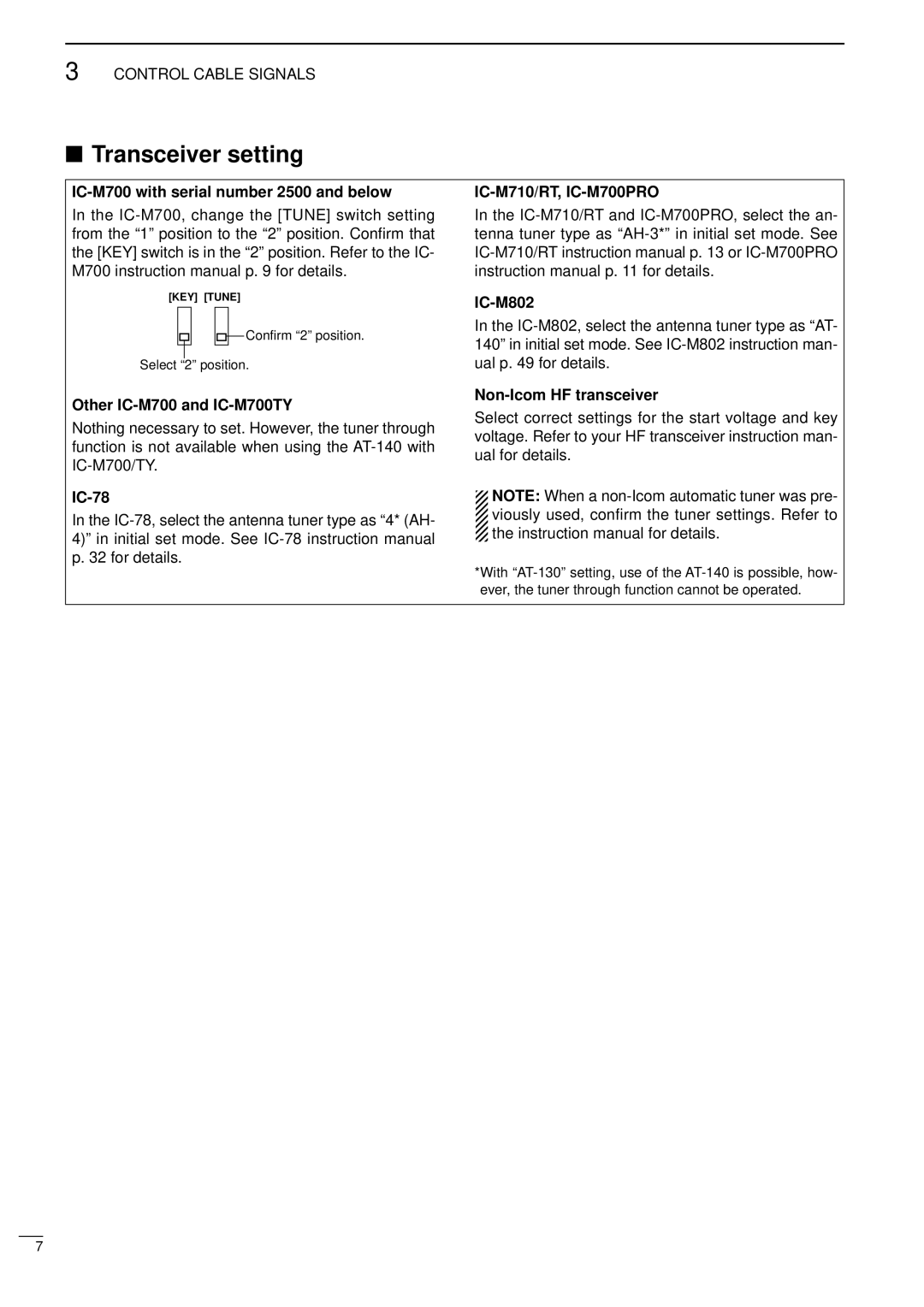
In the IC-M700, change the [TUNE] switch setting from the “1” position to the “2” position. Confirm that the [KEY] switch is in the “2” position. Refer to the IC- M700 instruction manual p. 9 for details.

[KEY] [TUNE]

Confirm “2” position.

Select “2” position.

Other IC-M700 and IC-M700TY

Nothing necessary to set. However, the tuner through function is not available when using the AT-140 with IC-M700/TY.

IC-78

In the IC-78, select the antenna tuner type as “4* (AH- 4)” in initial set mode. See IC-78 instruction manual p. 32 for details.

IC-M710/RT, IC-M700PRO

In the IC-M710/RT and IC-M700PRO, select the an- tenna tuner type as “AH-3*” in initial set mode. See IC-M710/RT instruction manual p. 13 or IC-M700PRO instruction manual p. 11 for details.

IC-M802

In the IC-M802, select the antenna tuner type as “AT- 140” in initial set mode. See IC-M802 instruction man- ual p. 49 for details.

Non-Icom HF transceiver

Select correct settings for the start voltage and key voltage. Refer to your HF transceiver instruction man- ual for details.

NOTE: When a non-Icom automatic tuner was pre-

viously used, confirm the tuner settings. Refer to the instruction manual for details.

*With “AT-130” setting, use of the AT-140 is possible, how- ever, the tuner through function cannot be operated.

7

Page 10
Image 10
Icom AT-140 instruction manual Transceiver setting, IC-M700 with serial number 2500 and below, Other IC-M700 and IC-M700TY