ASSEMBLY
Assembly requires two persons. Set the treadmill in a cleared area. Do not remove the cardboard from the area shown in drawing 2 below. Remove all other packing materials. Do not dispose of any packing materials until assembly is completed. Treadmill assembly requires the included allen wrench ![]() and your own phillips
and your own phillips
screwdriver | and 9/16” wrench | . |
Note: The underside of the treadmill walking belt is coated with
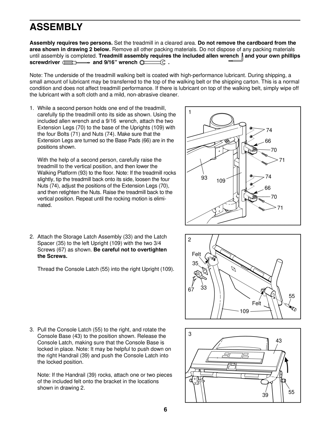
1.While a second person holds one end of the treadmill, carefully tip the treadmill onto its side as shown. Using the included allen wrench and a 9/16” wrench, attach the two Extension Legs (70) to the base of the Uprights (109) with the four Bolts (71) and Nuts (74). Make sure that the Extension Legs are turned so the Base Pads (66) are in the positions shown.
With the help of a second person, carefully raise the treadmill to the vertical position, and then lower the Walking Platform (93) to the floor. Note: If the treadmill rocks slightly, tip the treadmill back onto its side, loosen the four Nuts (74), adjust the positions of the Extension Legs (70), and then retighten the Nuts. Raise the treadmill back to the vertical position. Repeat until the rocking motion is elimi- nated.
2.Attach the Storage Latch Assembly (33) and the Latch Spacer (35) to the left Upright (109) with the two 3/4” Screws (67) as shown. Be careful not to overtighten the Screws.
Thread the Console Latch (55) into the right Upright (109).
3.Pull the Console Latch (55) to the right, and rotate the Console Base (43) to the position shown. Release the Console Latch, making sure that the Console Base is locked in place. Note: It may be helpful to push down on the right Handrail (39) and push the Console Latch into the locked position.
Note: If the Handrail (39) rocks, attach one or two pieces of the included felt onto the bracket in the locations shown in drawing 2.
1 |
|
|
|
|
| 74 |
|
|
| 66 |
|
|
| 70 |
|
|
| 71 |
|
| 93 | 74 |
|
|
| 109 |
|
|
| 66 |
|
|
| 70 |
|
|
| 71 |
|
2 |
|
|
|
Felt |
|
| |
35 |
|
|
|
67 | 33 |
|
|
|
|
| |
|
|
| 55 |
|
| Felt |
|
|
| 109 |
|
3 |
|
|
|
|
| 43 |
|
|
| 39 | 55 |
|
|
| |
6