5.4OVEN SYSTEMS
Right Lock Motor Assembly |
| e. | Select “Top Oven.” | |
The right lock motor assembly consists of a motor, |
| f. | Select “Mags.” For Gen 1 ovens, the Cook- | |
|
| Wheel must not be in the Off position. | ||
locking mechanism for the right side of the Speed- |
|
| ||
|
|
| ||
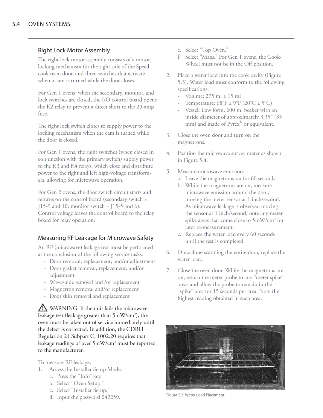
cook oven door, and three switches that activate | 2. | Place a water load into the cook cavity (Figure | ||
when a cam is turned while the door closes. |
| 5.3). Water load must conform to the following | ||
For Gen 1 ovens, when the secondary, monitor, and |
| specifications: | ||
| - | Volume: 275 ml ± 15 ml | ||
lock switches are closed, the I/O control board opens |
| |||
| - | Temperature: 68°F ± 9°F (20°C ± 5°C) | ||
the K2 relay to prevent a direct short to the |
| |||
| - | Vessel: Low form, 600 ml beaker with an | ||
fuse. |
| |||
|
| inside diameter of approximately 3.35” (85 | ||
|
|
| ||
The right lock switch closes to supply power to the |
|
| mm) and made of Pyrex® or equivalent. | |
locking mechanism when the cam is turned while | 3. | Close the oven door and turn on the | ||
the door is closed. | ||||
| magnetrons. | |||
|
| |||
For Gen 1 ovens, the right switches (when closed in | 4. | Position the microwave survey meter as shown | ||
conjunction with the primary switch) supply power |
| in Figure 5.4. | ||
to the K3 and K4 relays, which close and distribute | 5. | Measure microwave emission: | ||
power to the right and left | ||||
ers, allowing for microwave operation. |
| a. | Leave the magnetrons on for 60 seconds. | |
For Gen 2 ovens, the door switch circuit starts and |
| b. While the magnetrons are on, measure | ||
|
| microwave emission around the door, | ||
returns on the control board (secondary switch = |
|
| moving the meter sensor at 1 inch/second. | |
|
| As microwave leakage is observed moving | ||
Control voltage leaves the control board to the relay |
|
| the sensor at 1 inch/second, note any meter | |
board for relay operation. |
|
| spike areas that come close to 5mW/cm2 for | |
|
|
| later | |
Measuring RF Leakage for Microwave Safety |
| c. | Replace the water load every 60 seconds | |
|
| until the test is completed. | ||
An RF (microwave) leakage test must be performed |
|
| ||
6. | Once done scanning the entire door, replace the | |||
at the conclusion of the following service tasks: | ||||
| water load. | |||
- Door removal, replacement, and/or adjustment |
| |||
|
|
| ||
- Door gasket removal, replacement, and/or | 7. | Close the oven door. While the magnetrons are | ||
| ||||
adjustment | on, return the meter probe to any “meter spike” | |
- Waveguide removal and /or replacement | ||
areas and allow the probe to remain in the | ||
- Magnetron removal and/or replacement | ||
“spike” area for 15 seconds per area. Note the | ||
- Door skin removal and replacement | ||
highest reading obtained in each area. | ||
| ||
WARNING: If the unit fails the microwave |
| |
leakage test (leakage greater than 5mW/cm2), the |
| |
oven must be taken out of service immediately until |
| |
the defect is corrected. In addition, the CDRH |
| |
Regulation 21 Subpart C, 1002.20 requires that |
| |
leakage readings of over 5mW/cm2 must be reported |
| |
to the manufacturer. |
|
To measure RF leakage,
1.Access the Installer Setup Mode.
a.Press the “Info” key.
b.Select “Oven Setup.”
c.Select “Installer Setup.”
d. Input the password 042259. | Figure 5.3: Water Load Placement |
|