For the turbochef residential single and double wall ovens
Page
For further information, call 866.447.3783
TurboChef Technologies, Inc
Table Of Contents
Oven Controls and Cooking Lower Oven Double-Wall Oven Only
Info Mode
Oven Systems
RTD
Troubleshooting
RTD
Appendix Replacing Oven Components
Schematics
Safety Precautions
Read ALL Instructions Before Using
Grounding Instructions
Power Connections
Self-Cleaning Oven Guidelines
Surfaces of Oven
Iii
RF Interference Considerations
Iv Saftey Instructions
Section Specifications and Installation
Page
Certifications
Electrical Specifications
Theory of Operation
Catalytic Converter
Dimensions Single Wall Oven
Dimensions Double Wall Oven
Installation Safety Instructions
Installation
Cabinet Dimensions and Specifications, Double Wall Oven
Double Wall Oven Cabinet Dimensions
Single Wall Oven Cabinet Dimensions
Installing the Oven
Specifications and Installation
Section Oven Controls and Cooking Speedcook Oven
Page
Speedcook Oven Controls
Cook Modes
Cooking a Recently Prepared Dish
Favorites Cooking
Roast
Toast
Using the Convection Bake Function
Using the Defrost Function
Using the Microwave Function
Mode 1 Oven Off
Mode 2 Select a Food Item
Basic Cooking
Mode 6 Cooking
Mode 3 Confirm Settings
Mode 4 Preheat
Mode 5 Ready to Cook
Mode 9 Remove Food from Oven
Mode 8 100% Complete
Adjusting a Recipe’s Cook Time
Adjusting a Cook Temperature
Advanced Cook Mode
Saving to Favorites
495
Deleting a Dish from Favorites
Reheat Setting
Self-Clean Mode Speedcook Oven
Renaming a Dish in Favorites
Section Oven Controls and Cooking
Page
Lower Oven Controls
Convection Roast
Warm Setting
Proof Setting
Convection Bake
175
Sabbath Mode
Self-Clean Mode
Info Mode
Page
Adjusting Oven Sounds
Overview of the Info Mode
Adjusting the Oven’s Units & Measurements
Adjusting Display Settings
Backing Up/Restoring Favorites
Updating the Oven Software
Accessing the Version
Installer Setup
Information
Oven Systems
Page
Convection System Speedcook Oven
Convection System Lower Oven
Double Wall Oven Only
Speedcook Oven Door
Left Lock Motor Assembly
Door Skin Replacement
Measuring RF Leakage for Microwave Safety
Right Lock Motor Assembly
Halogen Light Assembly
Removing/Reinstalling the Lower Oven Door
Lower Oven Door Double Wall Oven Only
High-Voltage Capacitors
Halogen Bulb Replacement
Microwave System
Doubler Circuit, Voltage
High-Voltage Transformers
Magnetrons
Waveguides
CookWheel Control
Control System
Clock
Control Board
EMI Filter
Light Switch, Control Panel
Display, Speedcook Oven
Electrical Compartment Cooling Fans
Magnetron Thermostats
Power Supply, 12 VDC
Power Supply, 24 VDC
Magnetron Cooling Fan
Relay K13 L2 Lower Heating Elements Double Wall Oven Only
Selector Switches
Relay K9 L2 Speedcook Heating Elements
Relay K10 Lower Door Lock Gen 1 Oven
Thermostat, Cooling Fan Control
Temperature Switch Lower Oven
Speaker
Transformer, Clock, 12 VAC
Exhaust Blower
Wiring Harness
Exhaust System
Catalytic Converter
This page intentionally Left blank
Troubleshooting
Page
Overview of Troubleshooting
Error Screens
Oven Door Open Gen
Cooling Fan Failure Gen
Temperature Control Failure
Blower Failure
Magnetron Failure
Component Testing Troubleshooting
Oven Over Temperature
Control System
If voltage is present, the oven mode switch
RTD
Cooling System
Halogen Light System
Troubleshooting Cooling Fans Gen
Air Impingement System
Microwave System
Heating System, Speedcook Oven
No Heat
Turn the CookWheel to Bake to begin the preheat cycle
Heating System, Lower Oven
No Heat/Slow to Heat
Testing for a K11 SSR that is Stuck Open
This page intentionally Left blank
Section Oven Schematics
Page
TDO Upper Oven
TDO Bottom Oven Generation
CT1
TDO2 Upper Oven Generation
Relay Board REV D
TDO2 Bottom Oven Generation
TSO Oven Single Wall Oven
RWD/RWS GEN 2 Control Board Pin-out descriptions
Upper Left
Upper Right
This page intentionally Left blank
Appendix Replacing Oven Components
Page
Part Details Locate the Part Here
Comprehensive Table of Oven Components
Appendix Replacing Oven Components
Fuse, 20 Amp, Gen 100599 DWO Gen 100603
RTD
A.16, A.17, A.18
Removing the Oven
Component and Assembly Location, DWO Gen 1 and Gen
None See pages -A.25
Bracket, USB, Strap RWS-9026
Component and Assembly Location, SWO
Figure A.2 Component and Assembly Location, SWO
Front Trim Assembly Removal
Front Trim Assembly Detail
Bracket, Display, Lower RWD-9142 Screw, #8 x 1/2, PHPH, PLT
Bracket, Speaker RWD-9567
Control Housing Detail
Differentiating Between DWO Gen 1 and DWO Gen
Upper Electrical Compartment, DWO Gen
Blower, Dual 104164 Screw, SH MTL, #8 x 1/2 Serrated Phtrh
Appendix Replacing Oven Components
Upper Electrical Compartment, DWO Gen 2 and SWO
Appendix Replacing Oven Components
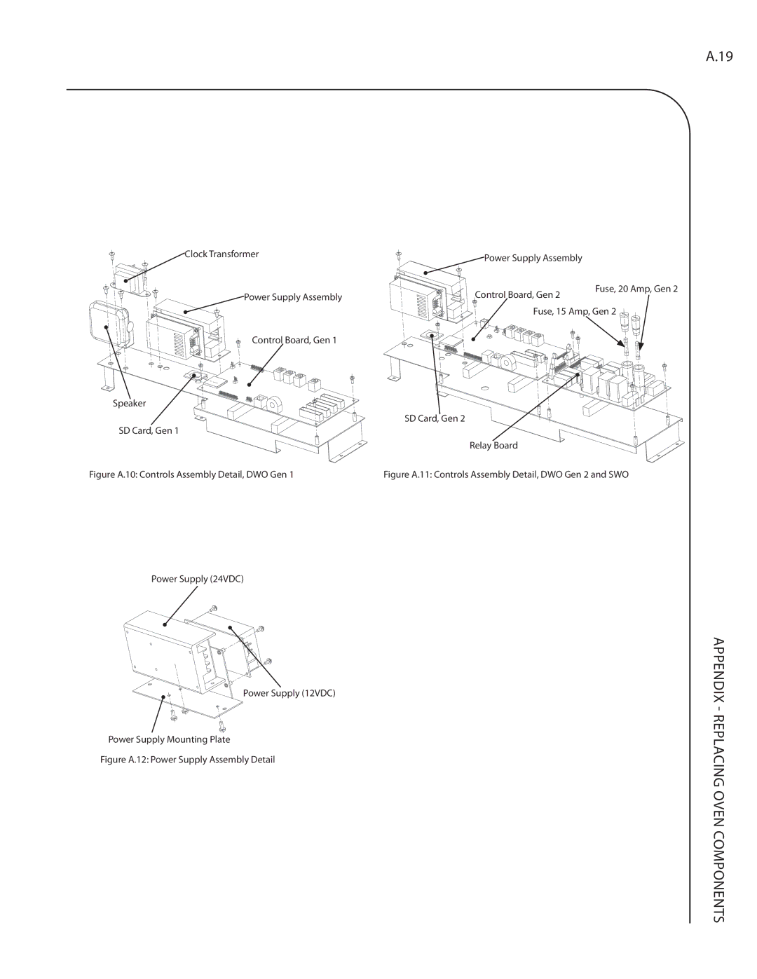
Controls Assembly Detail, DWO Gen 1, DWO Gen 2, and SWO
Figure A.11 Controls Assembly Detail, DWO Gen 2 and SWO
Item Description Item Hardware Description
Figure A.15 Relay Assembly Detail, DWO Gen
Lower Electrical Compartment Detail, DWO Gen 1 and DWO Gen
Figure A.19 Bracket, Relay Attachment Detail, Gen
104228 Screw, #6 x 1/2, PPHD, DRL-PT, SS 101687
Components
Appendix Replacing Oven Components
This page intentionally Left blank
Lower Oven Cavity Component Detail, DWO Gen 1 and DWO Gen
Figure A.25 Convection Fan Assembly Detail
This page intentionally Left blank
Page
For service or information