9.To install a new door, hold the door by the sides and slide the door into the hinge pockets in the same manner the door was removed.
10.Open the door completely.
11.Push both hinge locks back into their original positions.
12.Close the door.
13.Reinstall the locking screws, insulation, and insulation covers.
14.Ensure the door opens and closes freely.
15.Push the oven back into its original position.
16.Perform a MW leakage test (see page 5.4).
Door Skin Replacement
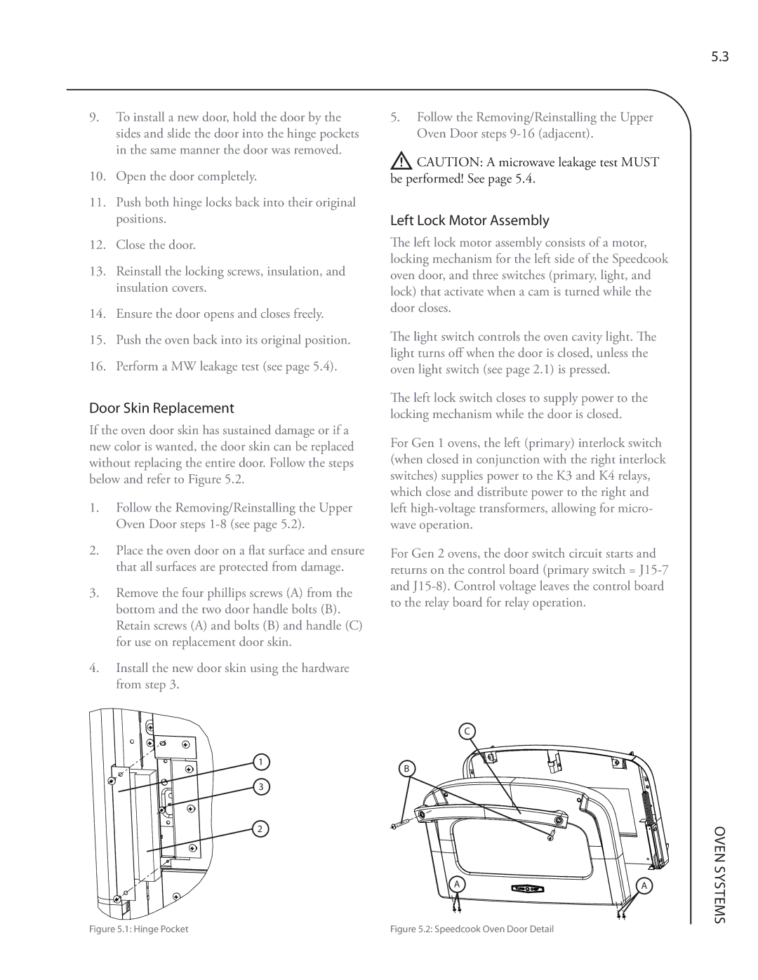
If the oven door skin has sustained damage or if a new color is wanted, the door skin can be replaced without replacing the entire door. Follow the steps below and refer to Figure 5.2.
1.Follow the Removing/Reinstalling the Upper Oven Door steps
2.Place the oven door on a flat surface and ensure that all surfaces are protected from damage.
3.Remove the four phillips screws (A) from the bottom and the two door handle bolts (B). Retain screws (A) and bolts (B) and handle (C) for use on replacement door skin.
4.Install the new door skin using the hardware from step 3.
5.Follow the Removing/Reinstalling the Upper Oven Door steps
![]() CAUTION: A microwave leakage test MUST be performed! See page 5.4.
CAUTION: A microwave leakage test MUST be performed! See page 5.4.
Left Lock Motor Assembly
The left lock motor assembly consists of a motor, locking mechanism for the left side of the Speedcook oven door, and three switches (primary, light, and lock) that activate when a cam is turned while the door closes.
The light switch controls the oven cavity light. The light turns off when the door is closed, unless the oven light switch (see page 2.1) is pressed.
The left lock switch closes to supply power to the locking mechanism while the door is closed.
For Gen 1 ovens, the left (primary) interlock switch (when closed in conjunction with the right interlock switches) supplies power to the K3 and K4 relays, which close and distribute power to the right and left
For Gen 2 ovens, the door switch circuit starts and returns on the control board (primary switch =
5.3
1
C
B
3
2
A![]()
![]()
![]()
![]()
![]()
![]()
![]()
![]() A
A
OVEN SYSTEMS
Figure 5.1: Hinge Pocket | Figure 5.2: Speedcook Oven Door Detail |