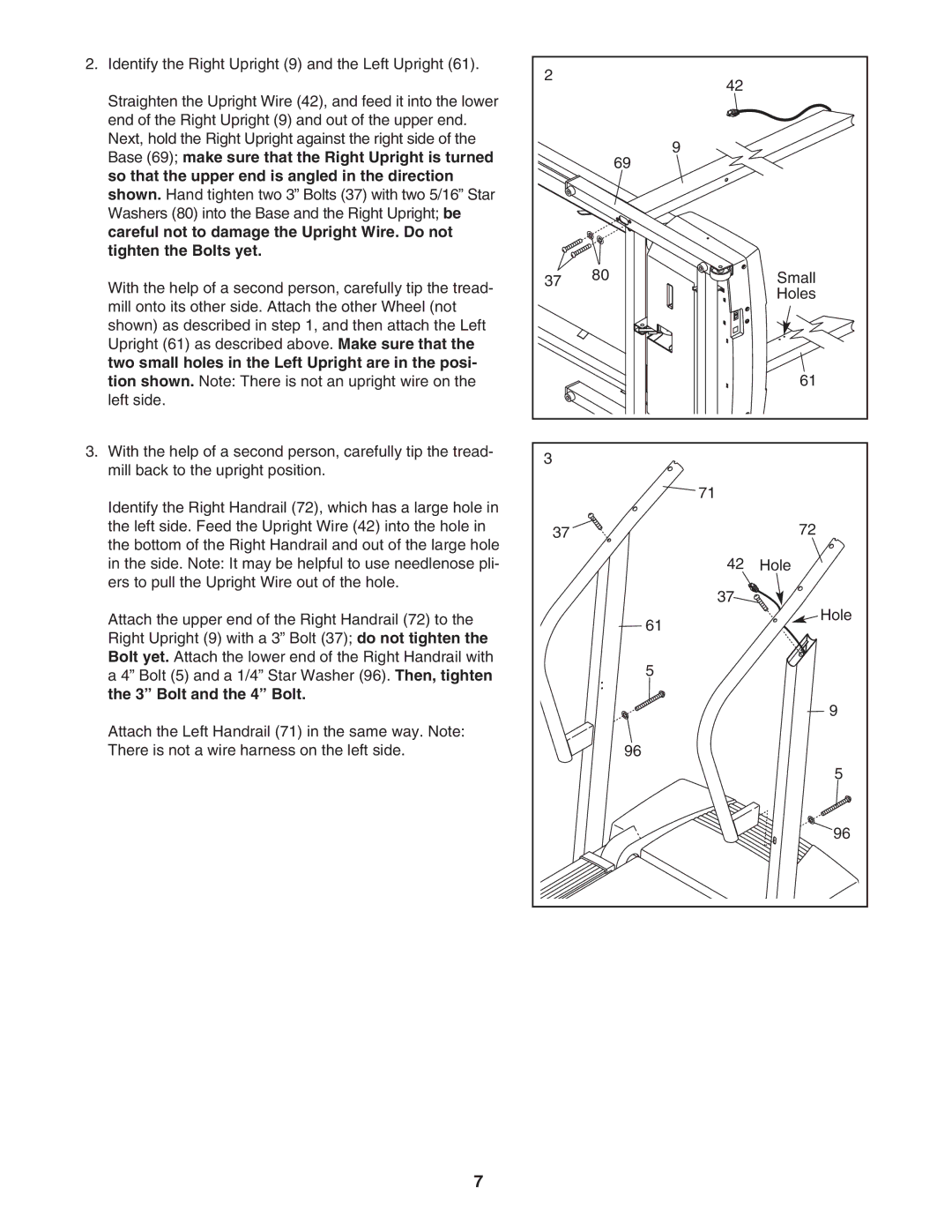
2.Identify the Right Upright (9) and the Left Upright (61).
Straighten the Upright Wire (42), and feed it into the lower end of the Right Upright (9) and out of the upper end. Next, hold the Right Upright against the right side of the Base (69); make sure that the Right Upright is turned so that the upper end is angled in the direction shown. Hand tighten two 3” Bolts (37) with two 5/16” Star Washers (80) into the Base and the Right Upright; be careful not to damage the Upright Wire. Do not tighten the Bolts yet.
With the help of a second person, carefully tip the tread- mill onto its other side. Attach the other Wheel (not shown) as described in step 1, and then attach the Left Upright (61) as described above. Make sure that the two small holes in the Left Upright are in the posi- tion shown. Note: There is not an upright wire on the left side.
3.With the help of a second person, carefully tip the tread- mill back to the upright position.
Identify the Right Handrail (72), which has a large hole in the left side. Feed the Upright Wire (42) into the hole in the bottom of the Right Handrail and out of the large hole in the side. Note: It may be helpful to use needlenose pli- ers to pull the Upright Wire out of the hole.
Attach the upper end of the Right Handrail (72) to the Right Upright (9) with a 3” Bolt (37); do not tighten the Bolt yet. Attach the lower end of the Right Handrail with a 4” Bolt (5) and a 1/4” Star Washer (96). Then, tighten the 3” Bolt and the 4” Bolt.
Attach the Left Handrail (71) in the same way. Note: There is not a wire harness on the left side.
2 | 42 |
|
|
| |
| 9 |
|
| 69 |
|
37 | 80 | Small |
|
| Holes |
|
| 61 |
3 |
|
|
| 71 |
|
37 |
| 72 |
| 42 | Hole |
| 37 |
|
| 61 | Hole |
|
| |
| 5 |
|
|
| 9 |
| 96 |
|
|
| 5 |
|
| 96 |
7