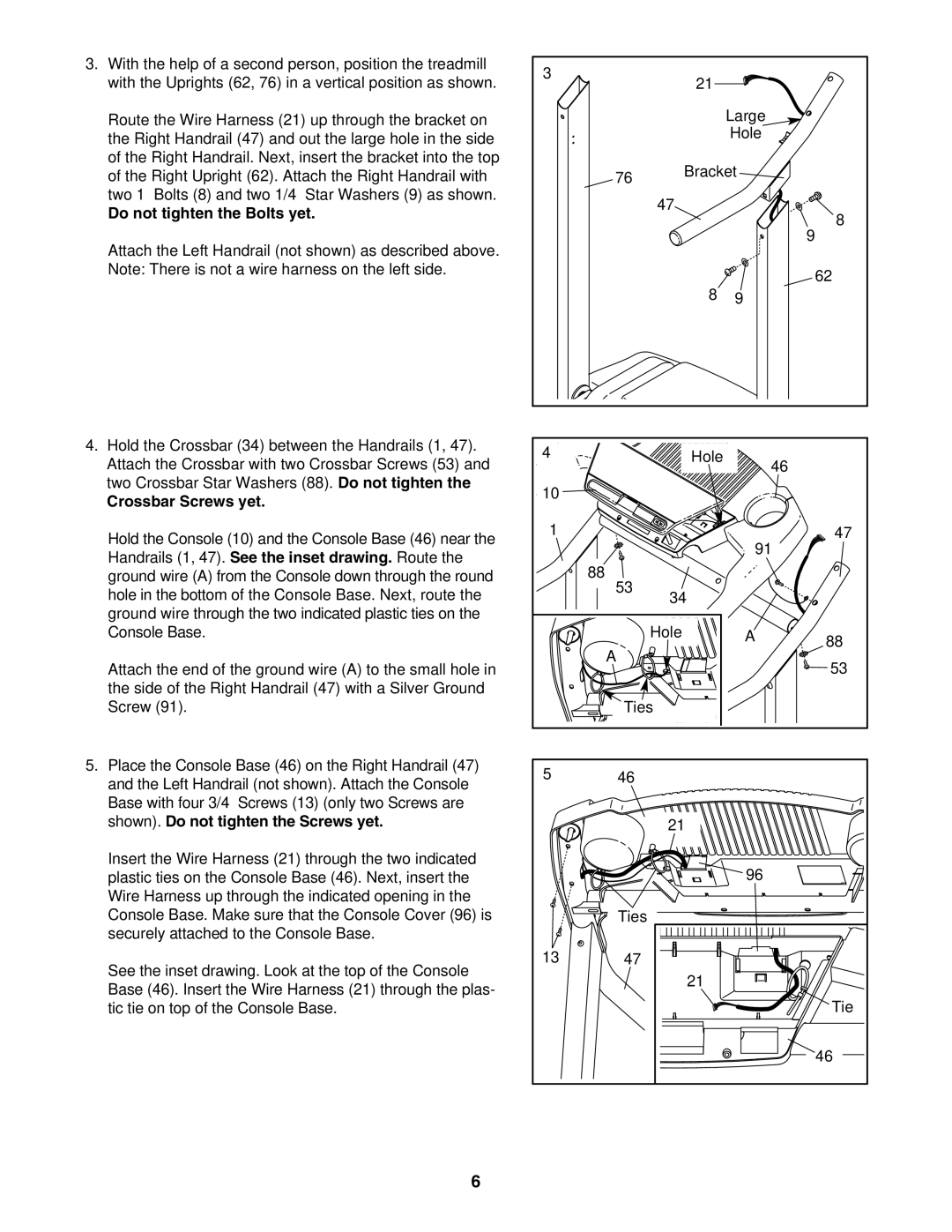
3. | With the help of a second person, position the treadmill | 3 |
|
|
|
|
| with the Uprights (62, 76) in a vertical position as shown. |
| 21 |
|
| |
|
|
|
|
| ||
| Route the Wire Harness (21) up through the bracket on |
|
|
| Large |
|
| the Right Handrail (47) and out the large hole in the side |
|
|
| Hole |
|
|
|
|
|
|
| |
| of the Right Handrail. Next, insert the bracket into the top |
|
| Bracket |
| |
| of the Right Upright (62). Attach the Right Handrail with |
| 76 |
| ||
| two 1” Bolts (8) and two 1/4” Star Washers (9) as shown. |
|
| 47 |
|
|
| Do not tighten the Bolts yet. |
|
|
| 8 | |
|
|
|
|
| ||
|
|
|
|
|
| |
| Attach the Left Handrail (not shown) as described above. |
|
|
|
| 9 |
|
|
|
|
|
| |
| Note: There is not a wire harness on the left side. |
|
|
|
| 62 |
|
|
|
|
|
| |
|
|
|
| 8 | 9 |
|
4. Hold the Crossbar (34) between the Handrails (1, 47). | 4 |
| Hole |
|
| |
| Attach the Crossbar with two Crossbar Screws (53) and |
| 46 |
| ||
|
|
|
|
| ||
| two Crossbar Star Washers (88). Do not tighten the | 10 |
|
|
|
|
| Crossbar Screws yet. |
|
|
|
| |
|
|
|
|
|
| |
| Hold the Console (10) and the Console Base (46) near the | 1 |
|
| 91 | 47 |
|
|
|
|
| ||
| Handrails (1, 47). See the inset drawing. Route the |
|
|
|
| |
|
| 88 |
|
|
| |
| ground wire (A) from the Console down through the round |
|
|
|
| |
| hole in the bottom of the Console Base. Next, route the |
| 53 | 34 |
|
|
|
|
|
|
| ||
| ground wire through the two indicated plastic ties on the |
|
|
|
|
|
| Console Base. |
|
| Hole | A | 88 |
|
|
| A |
|
| |
| Attach the end of the ground wire (A) to the small hole in |
|
|
| 53 | |
|
|
|
|
| ||
| the side of the Right Handrail (47) with a Silver Ground |
|
|
|
|
|
| Screw (91). |
| Ties |
|
| |
5. | Place the Console Base (46) on the Right Handrail (47) | 5 | 46 |
|
|
|
| and the Left Handrail (not shown). Attach the Console |
|
|
| ||
|
|
|
|
|
| |
| Base with four 3/4” Screws (13) (only two Screws are |
|
|
|
|
|
| shown). Do not tighten the Screws yet. |
|
| 21 |
|
|
| Insert the Wire Harness (21) through the two indicated |
|
|
| 96 |
|
| plastic ties on the Console Base (46). Next, insert the |
|
|
|
| |
| Wire Harness up through the indicated opening in the |
|
|
|
|
|
| Console Base. Make sure that the Console Cover (96) is |
| Ties |
|
|
|
| securely attached to the Console Base. |
|
|
|
|
|
| See the inset drawing. Look at the top of the Console | 13 | 47 |
|
|
|
|
|
| 21 |
|
| |
| Base (46). Insert the Wire Harness (21) through the plas- |
|
|
|
| |
|
|
|
|
| Tie | |
| tic tie on top of the Console Base. |
|
|
|
| |
|
|
|
|
|
| 46 |
6