ASSEMBLY
To hire an authorized service technician to assemble the treadmill, call
Assembly requires two persons. Set the treadmill in a cleared area and remove all packing materials. Do not dispose of the packing materials until assembly is completed. Note: The underside of the walking belt is coated with
Assembly requires the included allen wrenches | and your own phillips screwdriver | , | |
wire cutters | , adjustable wrench | , and needlenose pliers | . |
To identify the assembly hardware, see the PART IDENTIFICATION CHART in the center of this manual.
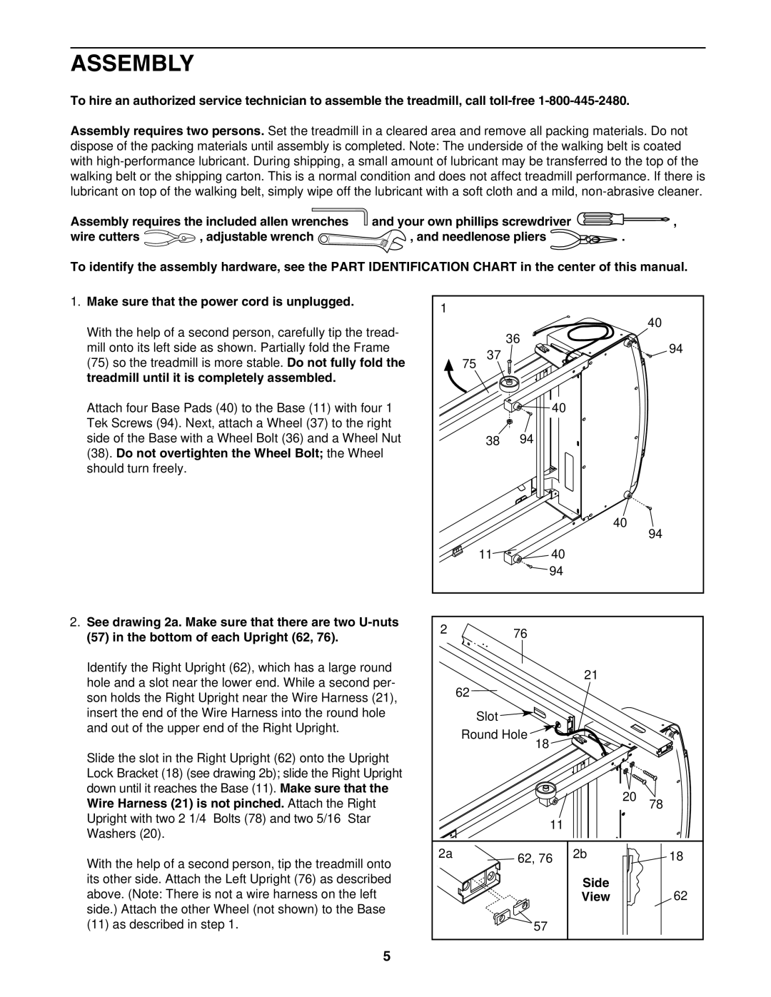
1.Make sure that the power cord is unplugged.
With the help of a second person, carefully tip the tread- mill onto its left side as shown. Partially fold the Frame (75) so the treadmill is more stable. Do not fully fold the treadmill until it is completely assembled.
Attach four Base Pads (40) to the Base (11) with four 1” Tek Screws (94). Next, attach a Wheel (37) to the right side of the Base with a Wheel Bolt (36) and a Wheel Nut (38). Do not overtighten the Wheel Bolt; the Wheel should turn freely.
2.See drawing 2a. Make sure that there are two
Identify the Right Upright (62), which has a large round hole and a slot near the lower end. While a second per- son holds the Right Upright near the Wire Harness (21), insert the end of the Wire Harness into the round hole and out of the upper end of the Right Upright.
Slide the slot in the Right Upright (62) onto the Upright Lock Bracket (18) (see drawing 2b); slide the Right Upright down until it reaches the Base (11). Make sure that the Wire Harness (21) is not pinched. Attach the Right Upright with two 2 1/4” Bolts (78) and two 5/16” Star Washers (20).
With the help of a second person, tip the treadmill onto its other side. Attach the Left Upright (76) as described above. (Note: There is not a wire harness on the left side.) Attach the other Wheel (not shown) to the Base (11) as described in step 1.
1 |
| 40 |
|
| |
|
| 36 |
| 37 | 94 |
75 |
| |
|
| 40 |
| 38 | 94 |
|
| 40 |
|
| 94 |
| 11 | 40 |
|
| 94 |
2 |
| 76 |
|
| |
|
| 21 |
62 |
|
|
Slot ![]()
Round Hole ![]()
18
|
| 20 | 78 |
| 11 |
|
|
2a | 62, 76 | 2b | 18 |
|
| Side | 62 |
|
| View | |
| 57 |
|
|
5