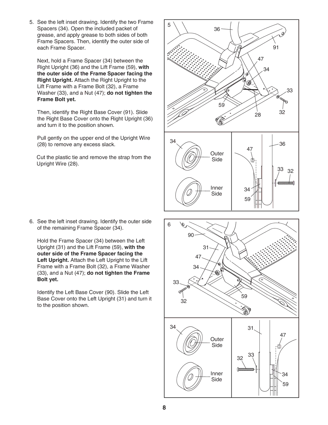
5. See the left inset drawing. Identify the two Frame | 5 |
|
|
|
|
Spacers (34). Open the included packet of | 36 |
|
|
| |
|
|
|
| ||
grease, and apply grease to both sides of both |
|
|
|
|
|
Frame Spacers. Then, identify the outer side of |
|
|
| 91 |
|
each Frame Spacer. |
|
|
|
| |
Next, hold a Frame Spacer (34) between the |
|
| 47 |
|
|
|
|
|
|
| |
Right Upright (36) and the Lift Frame (59), with |
|
| 34 |
|
|
the outer side of the Frame Spacer facing the |
|
|
|
| |
|
|
|
|
| |
Right Upright. Attach the Right Upright to the |
|
|
|
|
|
Lift Frame with a Frame Bolt (32), a Frame |
|
|
|
| 33 |
Washer (33), and a Nut (47); do not tighten the |
|
|
|
| |
|
|
|
|
| |
Frame Bolt yet. |
| 59 |
|
|
|
|
|
|
|
| |
Then, identify the Right Base Cover (91). Slide |
|
| 28 | 32 |
|
the Right Base Cover onto the Right Upright (36) |
|
|
|
| |
|
|
|
|
| |
and turn it to the position shown. |
|
|
|
|
|
Pull gently on the upper end of the Upright Wire | 34 |
|
| 36 |
|
(28) to remove any excess slack. |
|
|
| ||
|
| 47 |
| ||
|
| Outer |
|
| |
Cut the plastic tie and remove the strap from the |
|
|
|
| |
| Side |
|
|
| |
Upright Wire (28). |
|
|
|
| |
|
|
| 33 |
| |
|
|
|
| 32 | |
|
| Inner | 34 |
|
|
|
| Side |
|
| |
|
| 59 |
|
| |
|
|
|
|
| |
6. See the left inset drawing. Identify the outer side | 6 |
|
|
|
|
of the remaining Frame Spacer (34). |
|
|
|
| |
|
|
|
|
| |
Hold the Frame Spacer (34) between the Left |
| 90 |
|
|
|
|
|
|
|
| |
Upright (31) and the Lift Frame (59), with the |
| 31 |
|
|
|
outer side of the Frame Spacer facing the |
| 47 |
|
|
|
Left Upright. Attach the Left Upright to the Lift |
|
|
|
| |
|
|
|
|
| |
Frame with a Frame Bolt (32), a Frame Washer |
| 34 |
|
|
|
(33), and a Nut (47); do not tighten the Frame |
|
|
|
|
|
Bolt yet. | 33 |
|
|
|
|
|
|
|
|
| |
Identify the Left Base Cover (90). Slide the Left |
| 59 |
|
| |
Base Cover onto the Left Upright (31) and turn it |
|
|
| ||
| 32 |
|
|
| |
to the position shown. |
|
|
|
| |
|
|
|
|
| |
| 34 |
| 31 |
|
|
|
| Outer |
| 47 |
|
|
|
|
|
| |
|
| Side |
|
|
|
|
| 32 | 33 |
|
|
|
| Inner |
| 34 | |
|
| Side |
| 59 | |
|
|
|
| ||
| 8 |
|
|
|
|