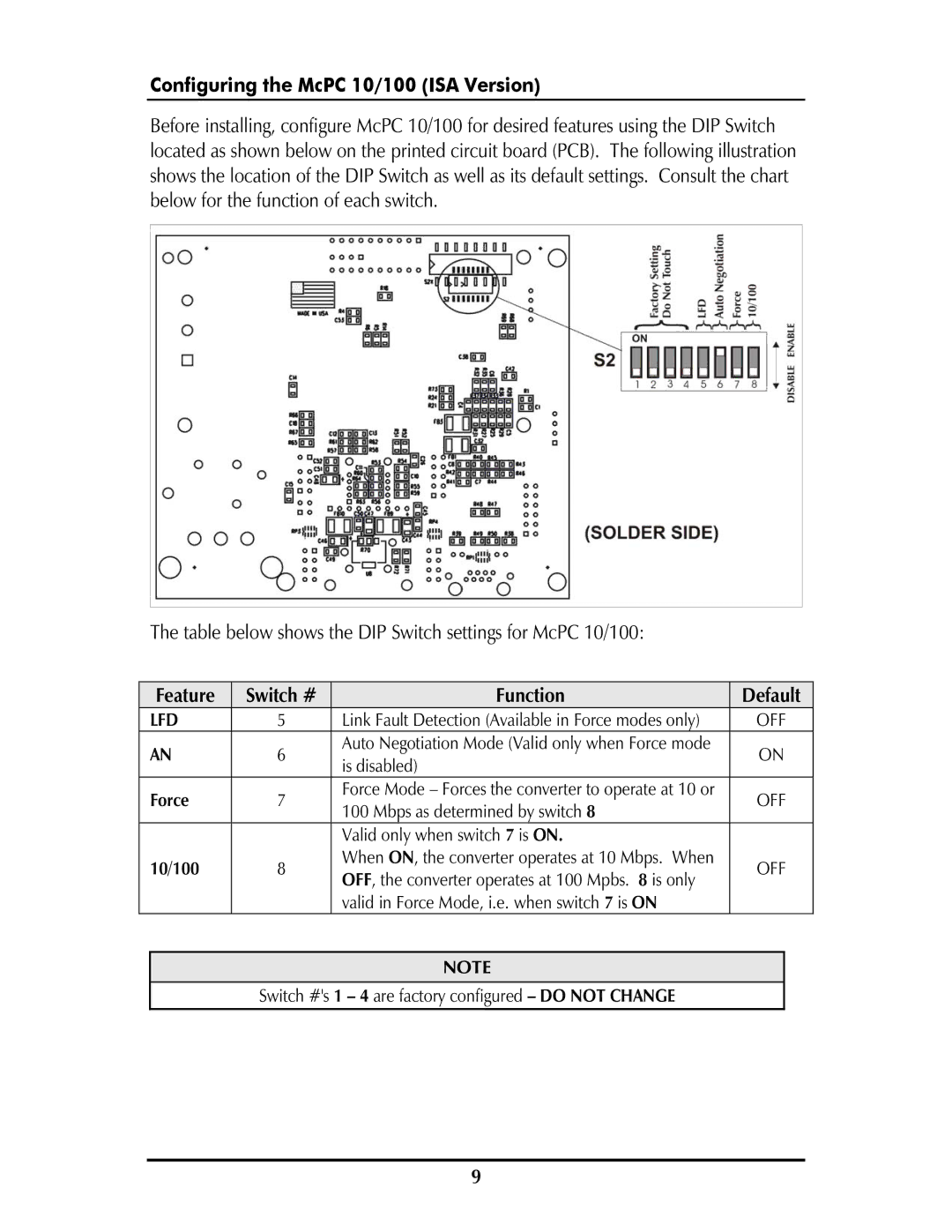
MCPC 10/100 specifications
IMC Networks has long been a trusted name in the field of networking solutions, particularly known for its commitment to producing reliable, high-quality equipment. One of its standout products is the MCPC 10/100 media converter, a versatile device designed to facilitate seamless communication in networks that require efficient data transmission over various types of media.The MCPC 10/100 media converter primarily serves the purpose of converting Ethernet signals between twisted-pair cabling and fiber optic connections. With the rise of fiber optic technology, businesses are increasingly adopting such media converters to ensure that they can leverage both the speed offered by fiber optics and the compatibility of traditional copper cabling. The MCPC allows for a smooth transition between these two media types without compromising data integrity or speed.
A key feature of the MCPC 10/100 is its ability to support both 10BASE-T and 100BASE-TX Ethernet standards. This dual compatibility makes it suitable for legacy and modern network infrastructures alike, allowing enterprises to maintain existing systems while upgrading to more advanced technology.
In terms of performance, the MCPC delivers impressive data transfer rates of up to 100 Mbps, facilitating efficient data handling and ensuring smooth connectivity across various network segments. It supports autonegotiation, which enables the converter to automatically adjust to the highest possible connection speed and compatibility.
Another important characteristic of the MCPC 10/100 is its compact design. The unit's small form factor allows for easy installation in various environments, whether it is within a rack or mounted on a wall. Additionally, it features LED indicators that provide real-time feedback regarding power status and link activity, making troubleshooting straightforward.
The MCPC is also designed for durability and reliability, with a robust construction that can withstand the rigors of industrial environments. It often includes features like surge protection and a wide operating temperature range, ensuring that it can function effectively in diverse conditions.
In conclusion, the IMC Networks MCPC 10/100 media converter is an essential tool for any organization looking to enhance its networking capabilities. Its flexibility, high performance, and solid build quality make it an ideal choice for bridging the gap between copper and fiber networks, thus aiding in the efficient management of data transmission across varied infrastructures.

