ASSEMBLY INSTRUCTION
Tools Required to Assemble the Machine: Two Adjustable Wrenches and Allen Wrenches
NOTE: It is strongly recommended this machine be assembled by two or more people to avoid possible injury.
STEP 1 (See Diagram 1)
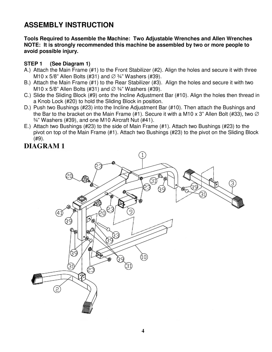
A.) Attach the Main Frame (#1) to the Front Stabilizer (#2). Align the holes and secure it with three M10 x 5/8” Allen Bolts (#31) and ∅ ¾” Washers (#39).
B.) Attach the Main Frame (#1) to the Rear Stabilizer (#3). Align the holes and secure it with two M10 x 5/8” Allen Bolts (#31) and ∅ ¾” Washers (#39).
C.) Slide the Sliding Block (#9) onto the Incline Adjustment Bar (#10). Align the holes then thread in a Knob Lock (#20) to hold the Sliding Block in position.
D.) Push two Bushings (#23) into the Incline Adjustment Bar (#10). Then attach the Bushings and the Bar to the bracket on the Main Frame (#1). Secure it with a M10 x 3” Allen Bolt (#33), two ∅ ¾” Washers (#39), and one M10 Aircraft Nut (#41).
E.) Attach two Bushings (#23) to the side of Main Frame (#1). Attach two Bushings (#23) to the pivot on top of the Main Frame (#1). Attach two Bushings (#23) to the pivot on the Sliding Block (#9).
DIAGRAM 1
4