STEP 7 (See Diagram 7)
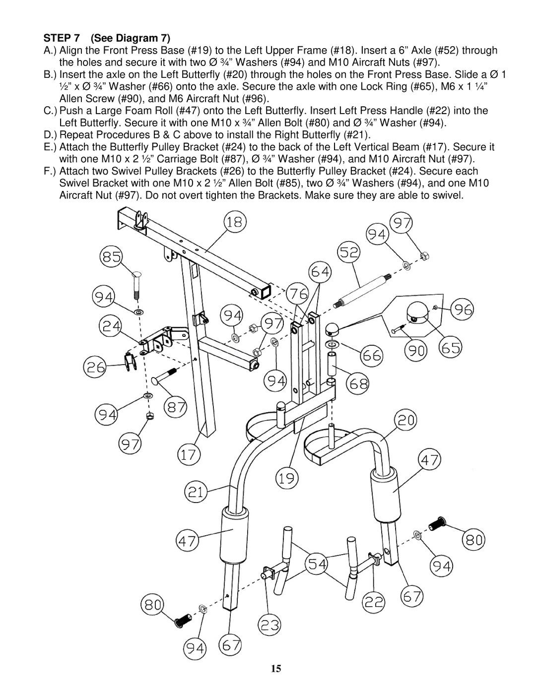
A.) Align the Front Press Base (#19) to the Left Upper Frame (#18). Insert a 6” Axle (#52) through the holes and secure it with two Ø ¾” Washers (#94) and M10 Aircraft Nuts (#97).
B.) Insert the axle on the Left Butterfly (#20) through the holes on the Front Press Base. Slide a Ø 1 ½” x Ø ¾” Washer (#66) onto the axle. Secure the axle with one Lock Ring (#65), M6 x 1 ¼” Allen Screw (#90), and M6 Aircraft Nut (#96).
C.) Push a Large Foam Roll (#47) onto the Left Butterfly. Insert Left Press Handle (#22) into the Left Butterfly. Secure it with one M10 x ¾” Allen Bolt (#80) and Ø ¾” Washer (#94).
D.) Repeat Procedures B & C above to install the Right Butterfly (#21).
E.) Attach the Butterfly Pulley Bracket (#24) to the back of the Left Vertical Beam (#17). Secure it with one M10 x 2 ½” Carriage Bolt (#87), Ø ¾” Washer (#94), and M10 Aircraft Nut (#97).
F.) Attach two Swivel Pulley Brackets (#26) to the Butterfly Pulley Bracket (#24). Secure each Swivel Bracket with one M10 x 2 ½” Allen Bolt (#85), two Ø ¾” Washers (#94), and one M10 Aircraft Nut (#97). Do not overt tighten the Brackets. Make sure they are able to swivel.
15