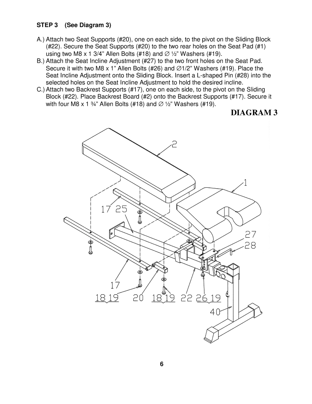
STEP 3 (See Diagram 3)
A.) Attach two Seat Supports (#20), one on each side, to the pivot on the Sliding Block (#22). Secure the Seat Supports (#20) to the two rear holes on the Seat Pad (#1) using two M8 x 1 3/4” Allen Bolts (#18) and ∅ ½” Washers (#19).
B.) Attach the Seat Incline Adjustment (#27) to the two front holes on the Seat Pad. Secure it with two M8 x 1” Allen Bolts (#26) and ∅ 1/2” Washers (#19). Place the Seat Incline Adjustment onto the Sliding Block. Insert a
C.) Attach two Backrest Supports (#17), one on each side, to the pivot on the Sliding Block (#22). Place Backrest Board (#2) onto the Backrest Supports (#17). Secure it with four M8 x 1 ¾” Allen Bolts (#18) and ∅ ½” Washers (#19).
DIAGRAM 3
6