ASSEMBLY INSTRUCTION
Tools Required Assembling the Machine: Adjustable Wrench, Allen Wrench and Hammer
NOTE: It is strongly recommended this machine to be assembled by two or more people to avoid possible injury.
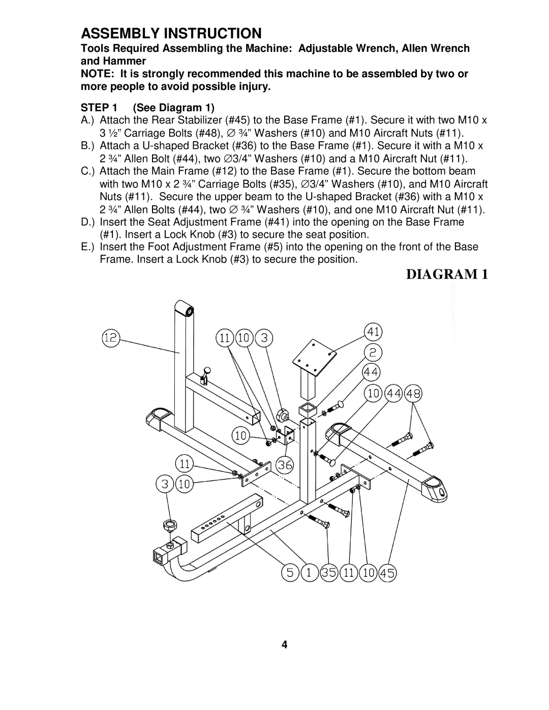
STEP 1 (See Diagram 1)
A.) Attach the Rear Stabilizer (#45) to the Base Frame (#1). Secure it with two M10 x 3 ½” Carriage Bolts (#48), ∅ ¾” Washers (#10) and M10 Aircraft Nuts (#11).
B.) Attach a
C.) Attach the Main Frame (#12) to the Base Frame (#1). Secure the bottom beam with two M10 x 2 ¾” Carriage Bolts (#35), ∅ 3/4” Washers (#10), and M10 Aircraft Nuts (#11). Secure the upper beam to the
D.) Insert the Seat Adjustment Frame (#41) into the opening on the Base Frame (#1). Insert a Lock Knob (#3) to secure the seat position.
E.) Insert the Foot Adjustment Frame (#5) into the opening on the front of the Base Frame. Insert a Lock Knob (#3) to secure the position.
DIAGRAM 1
4