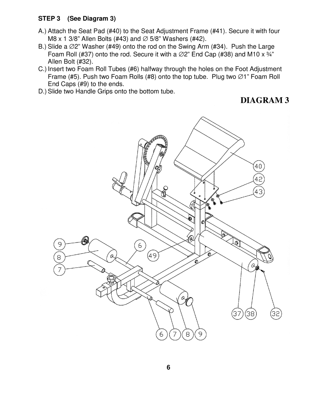
STEP 3 (See Diagram 3)
A.) Attach the Seat Pad (#40) to the Seat Adjustment Frame (#41). Secure it with four M8 x 1 3/8” Allen Bolts (#43) and ∅ 5/8” Washers (#42).
B.) Slide a ∅ 2” Washer (#49) onto the rod on the Swing Arm (#34). Push the Large Foam Roll (#37) onto the rod. Secure it with a ∅ 2” End Cap (#38) and M10 x ¾” Allen Bolt (#32).
C.) Insert two Foam Roll Tubes (#6) halfway through the holes on the Foot Adjustment Frame (#5). Push two Foam Rolls (#8) onto the top tube. Plug two ∅ 1” Foam Roll End Caps (#9) to the ends.
D.) Slide two Handle Grips onto the bottom tube.
DIAGRAM 3
6