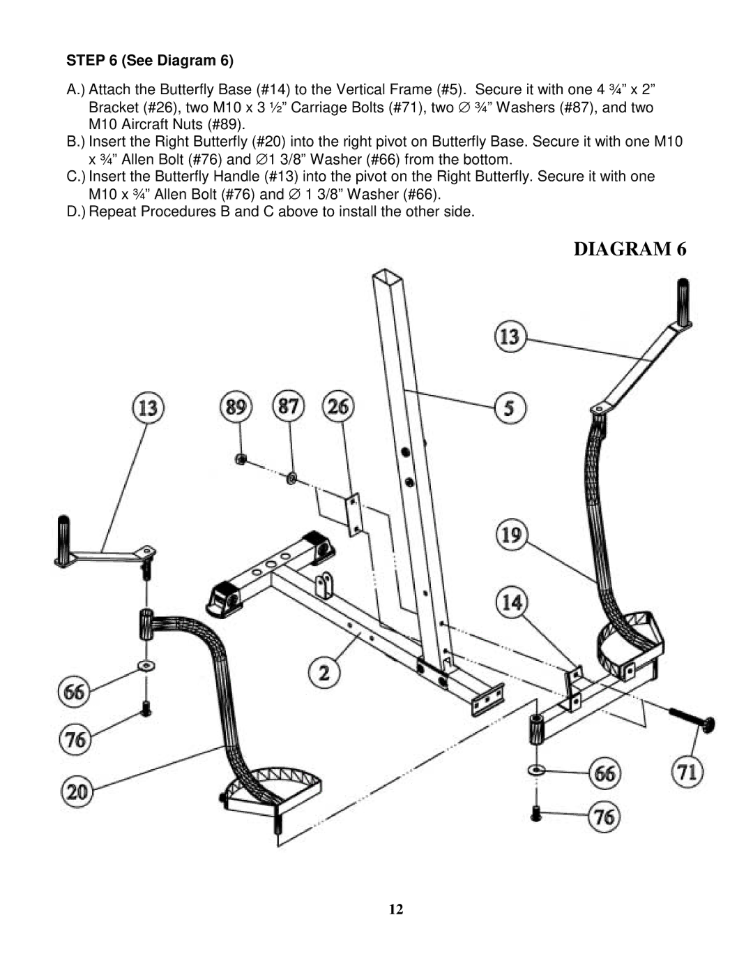
STEP 6 (See Diagram 6)
A.) Attach the Butterfly Base (#14) to the Vertical Frame (#5). Secure it with one 4 ¾” x 2” Bracket (#26), two M10 x 3 ½” Carriage Bolts (#71), two ∅ ¾” Washers (#87), and two M10 Aircraft Nuts (#89).
B.) Insert the Right Butterfly (#20) into the right pivot on Butterfly Base. Secure it with one M10 x ¾” Allen Bolt (#76) and ∅ 1 3/8” Washer (#66) from the bottom.
C.) Insert the Butterfly Handle (#13) into the pivot on the Right Butterfly. Secure it with one M10 x ¾” Allen Bolt (#76) and ∅ 1 3/8” Washer (#66).
D.) Repeat Procedures B and C above to install the other side.
DIAGRAM 6
12