STEP 4 (See Diagram 4)
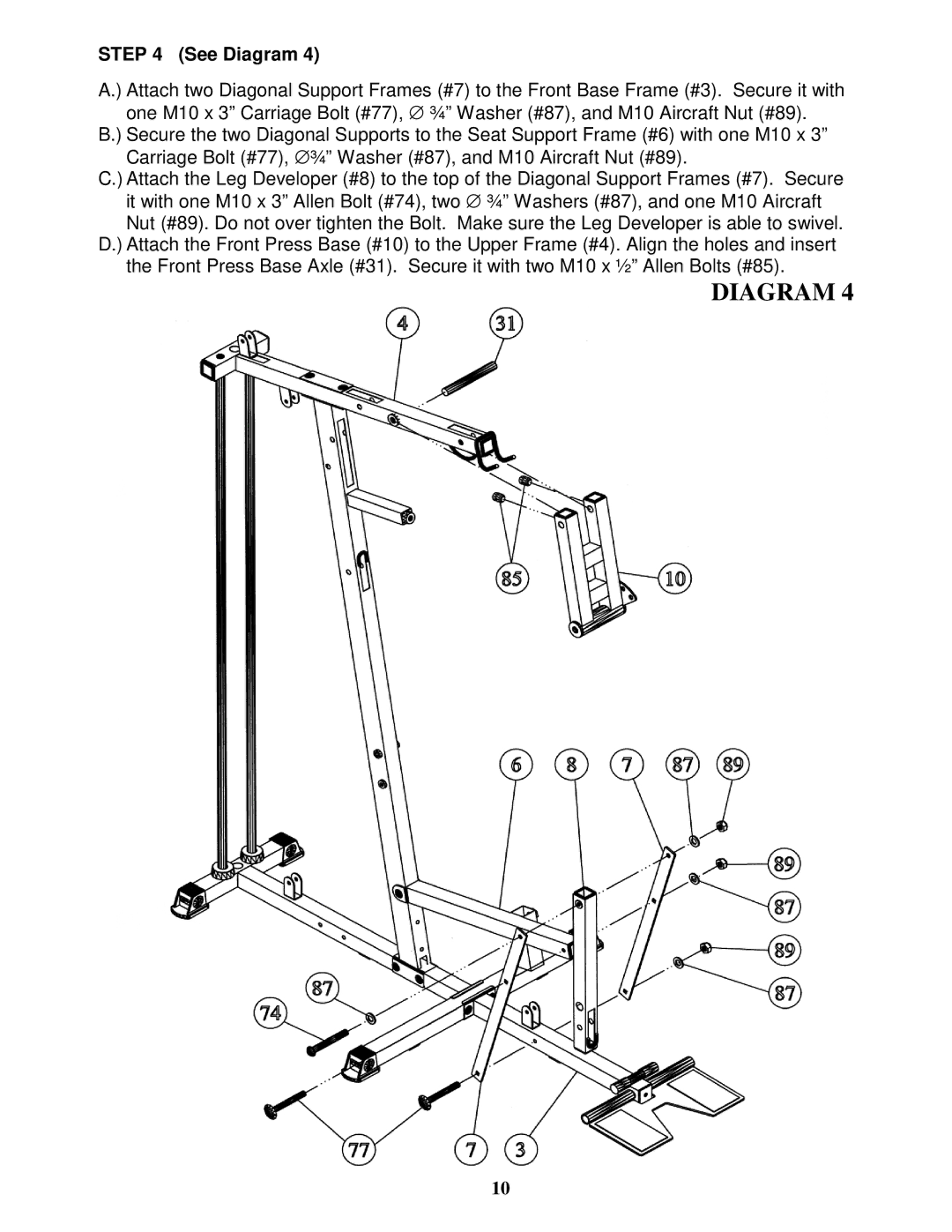
A.) Attach two Diagonal Support Frames (#7) to the Front Base Frame (#3). Secure it with one M10 x 3” Carriage Bolt (#77), ∅ ¾” Washer (#87), and M10 Aircraft Nut (#89).
B.) Secure the two Diagonal Supports to the Seat Support Frame (#6) with one M10 x 3” Carriage Bolt (#77), ∅ ¾” Washer (#87), and M10 Aircraft Nut (#89).
C.) Attach the Leg Developer (#8) to the top of the Diagonal Support Frames (#7). Secure it with one M10 x 3” Allen Bolt (#74), two ∅ ¾” Washers (#87), and one M10 Aircraft Nut (#89). Do not over tighten the Bolt. Make sure the Leg Developer is able to swivel.
D.) Attach the Front Press Base (#10) to the Upper Frame (#4). Align the holes and insert the Front Press Base Axle (#31). Secure it with two M10 x ½” Allen Bolts (#85).
DIAGRAM 4
10