ASSEMBLY INSTRUCTION
Tools Required Assembling the Machine: Two Adjustable Wrenches and Allen Wrenches
NOTE: It is strongly recommended this machine be assembled by two or more people to avoid possible injury.
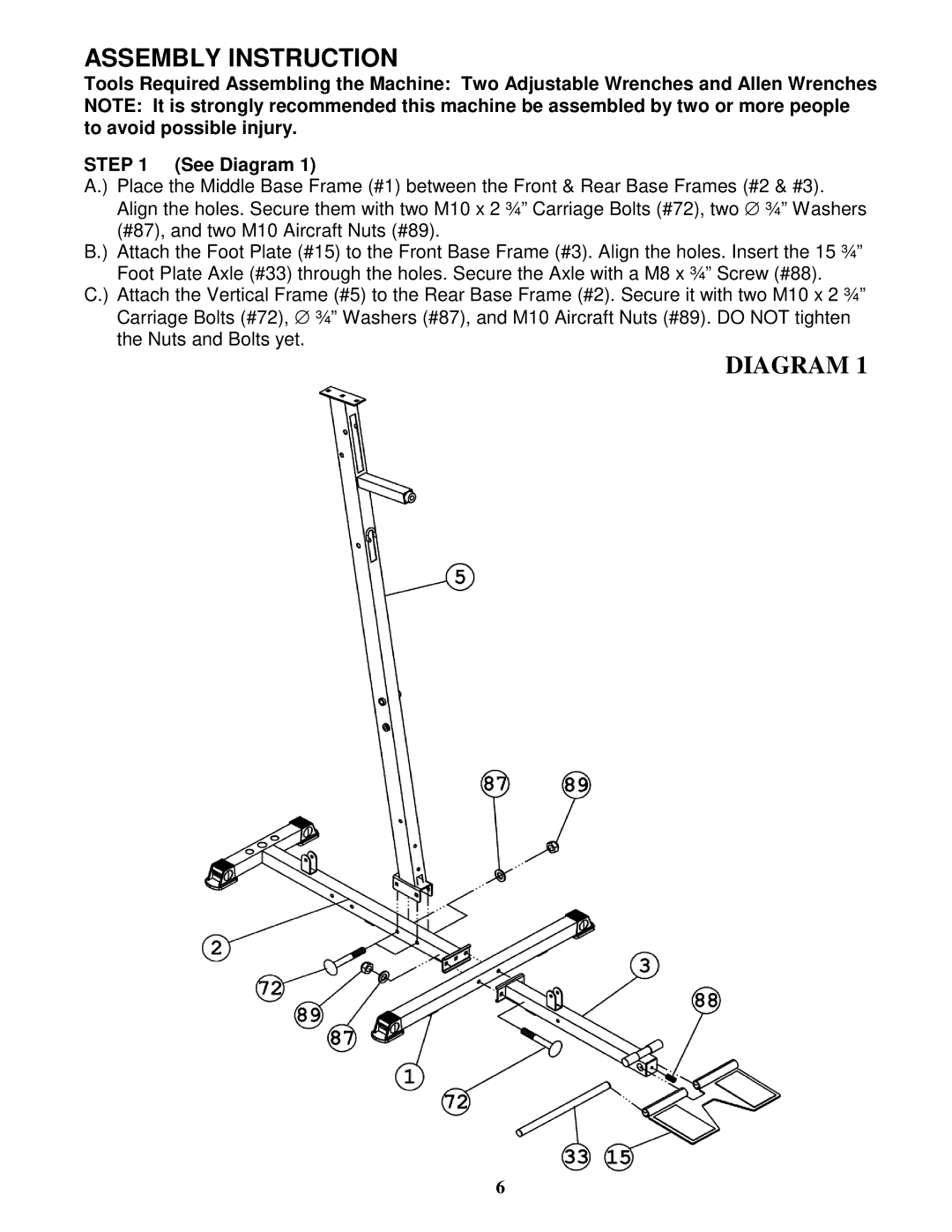
STEP 1 (See Diagram 1)
A.) Place the Middle Base Frame (#1) between the Front & Rear Base Frames (#2 & #3). Align the holes. Secure them with two M10 x 2 ¾” Carriage Bolts (#72), two ∅ ¾” Washers (#87), and two M10 Aircraft Nuts (#89).
B.) Attach the Foot Plate (#15) to the Front Base Frame (#3). Align the holes. Insert the 15 ¾” Foot Plate Axle (#33) through the holes. Secure the Axle with a M8 x ¾” Screw (#88).
C.) Attach the Vertical Frame (#5) to the Rear Base Frame (#2). Secure it with two M10 x 2 ¾” Carriage Bolts (#72), ∅ ¾” Washers (#87), and M10 Aircraft Nuts (#89). DO NOT tighten the Nuts and Bolts yet.
DIAGRAM 1
6