STEP 3 (See Diagram 3)
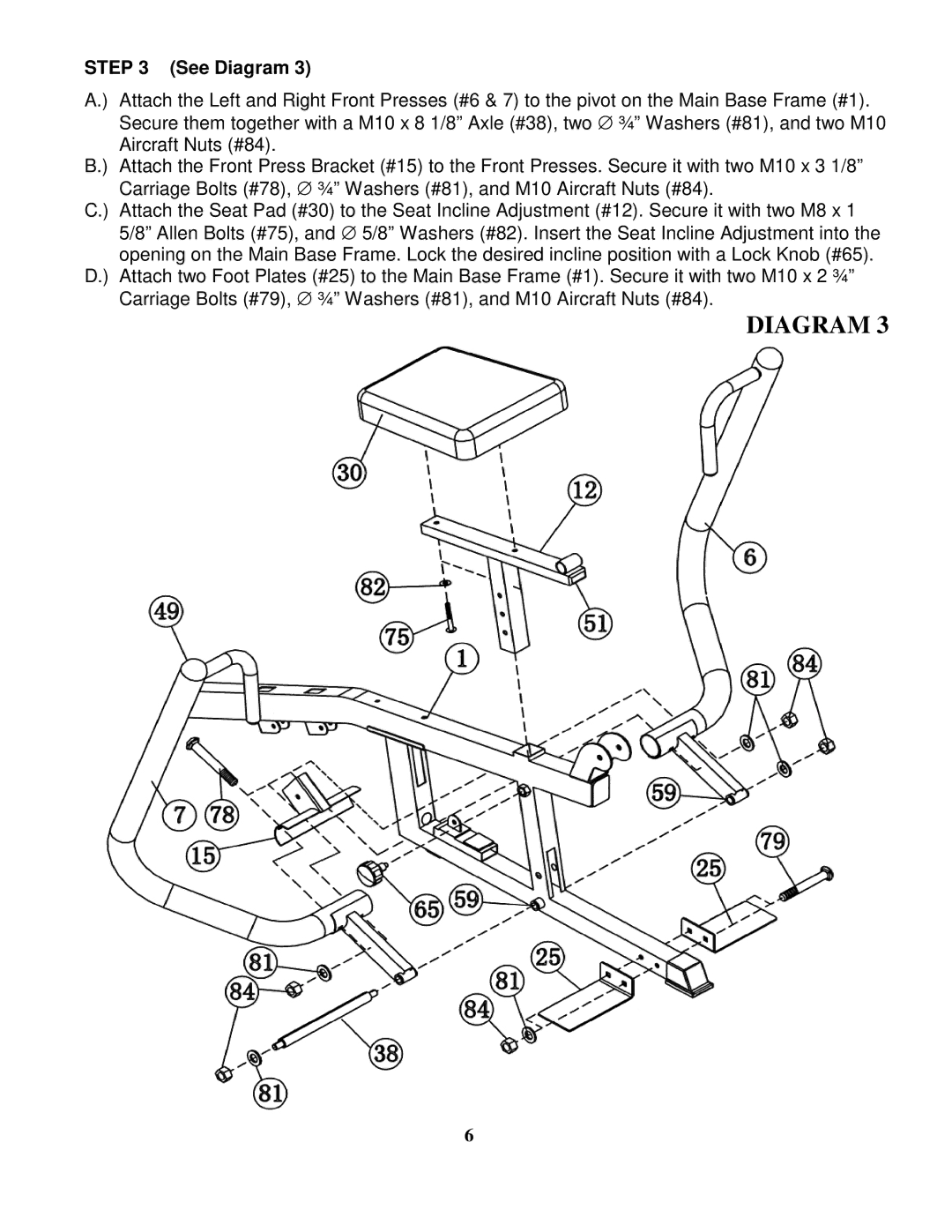
A.) Attach the Left and Right Front Presses (#6 & 7) to the pivot on the Main Base Frame (#1). Secure them together with a M10 x 8 1/8” Axle (#38), two ∅ ¾” Washers (#81), and two M10 Aircraft Nuts (#84).
B.) Attach the Front Press Bracket (#15) to the Front Presses. Secure it with two M10 x 3 1/8” Carriage Bolts (#78), ∅ ¾” Washers (#81), and M10 Aircraft Nuts (#84).
C.) Attach the Seat Pad (#30) to the Seat Incline Adjustment (#12). Secure it with two M8 x 1 5/8” Allen Bolts (#75), and ∅ 5/8” Washers (#82). Insert the Seat Incline Adjustment into the opening on the Main Base Frame. Lock the desired incline position with a Lock Knob (#65).
D.) Attach two Foot Plates (#25) to the Main Base Frame (#1). Secure it with two M10 x 2 ¾” Carriage Bolts (#79), ∅ ¾” Washers (#81), and M10 Aircraft Nuts (#84).
DIAGRAM 3
6