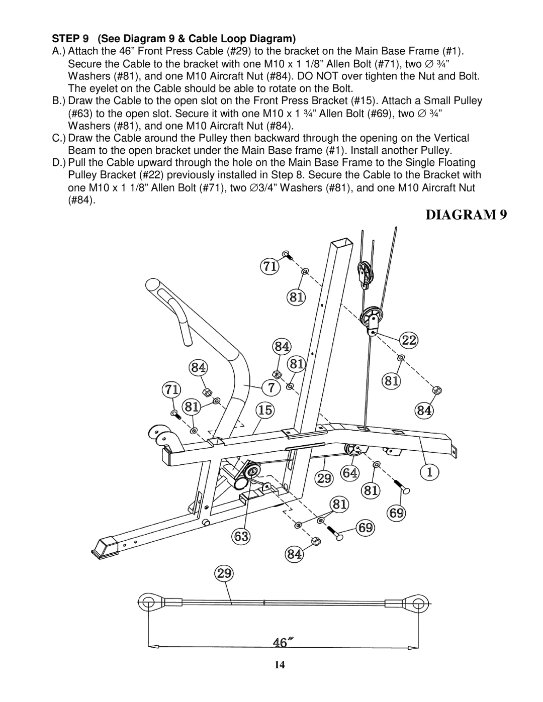
STEP 9 (See Diagram 9 & Cable Loop Diagram)
A.) Attach the 46” Front Press Cable (#29) to the bracket on the Main Base Frame (#1). Secure the Cable to the bracket with one M10 x 1 1/8” Allen Bolt (#71), two ∅ ¾” Washers (#81), and one M10 Aircraft Nut (#84). DO NOT over tighten the Nut and Bolt. The eyelet on the Cable should be able to rotate on the Bolt.
B.) Draw the Cable to the open slot on the Front Press Bracket (#15). Attach a Small Pulley (#63) to the open slot. Secure it with one M10 x 1 ¾” Allen Bolt (#69), two ∅ ¾” Washers (#81), and one M10 Aircraft Nut (#84).
C.) Draw the Cable around the Pulley then backward through the opening on the Vertical
Beam to the open bracket under the Main Base frame (#1). Install another Pulley.
D.) Pull the Cable upward through the hole on the Main Base Frame to the Single Floating Pulley Bracket (#22) previously installed in Step 8. Secure the Cable to the Bracket with one M10 x 1 1/8” Allen Bolt (#71), two ∅ 3/4” Washers (#81), and one M10 Aircraft Nut (#84).
DIAGRAM 9
14