ASSEMBLY INSTRUCTION
Tools Required Assembling the Machine: Two Adjustable Wrenches and Allen
Wrenches. NOTE: It is strongly recommended this machine to be assembled by two or more people to avoid possible injury.
STEP 1 (See Diagram 1) |
| |
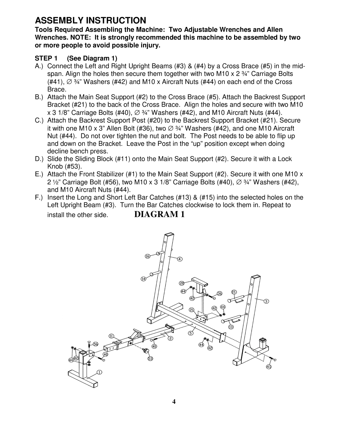
A.) | Connect the Left and Right Upright Beams (#3) & (#4) by a Cross Brace (#5) in the mid- | |
| span. Align the holes then secure them together with two M10 x 2 ¾” Carriage Bolts | |
| (#41), ∅ ¾” Washers (#42) and M10 x Aircraft Nuts (#44) on each end of the Cross | |
| Brace. |
|
B.) | Attach the Main Seat Support (#2) to the Cross Brace (#5). Attach the Backrest Support | |
| Bracket (#21) to the back of the Cross Brace. Align the holes and secure with two M10 | |
| x 3 1/8” Carriage Bolts (#40), ∅ ¾” Washers (#42), and M10 Aircraft Nuts (#44). | |
C.) | Attach the Backrest Support Post (#20) to the Backrest Support Bracket (#21). Secure | |
| it with one M10 x 3” Allen Bolt (#36), two ∅ ¾” Washers (#42), and one M10 Aircraft | |
| Nut (#44). Do not over tighten the nut and bolt. The Post needs to be able to flip up | |
| and down on the Bracket. Leave the Post in the “up” position except when doing | |
| decline bench press. |
|
D.) | Slide the Sliding Block (#11) onto the Main Seat Support (#2). Secure it with a Lock | |
| Knob (#53). |
|
E.) | Attach the Front Stabilizer (#1) to the Main Seat Support (#2). Secure it with one M10 x | |
| 2 ½” Carriage Bolt (#56), two M10 x 3 1/8” Carriage Bolts (#40), ∅ ¾” Washers (#42), | |
| and M10 Aircraft Nuts (#44). |
|
F.) | Insert the Long and Short Left Bar Catches (#13) & (#15) into the selected holes on the | |
| Left Upright Beam (#3). Turn the Bar Catches clockwise to lock them in. Repeat to | |
| install the other side. | DIAGRAM 1 |
4