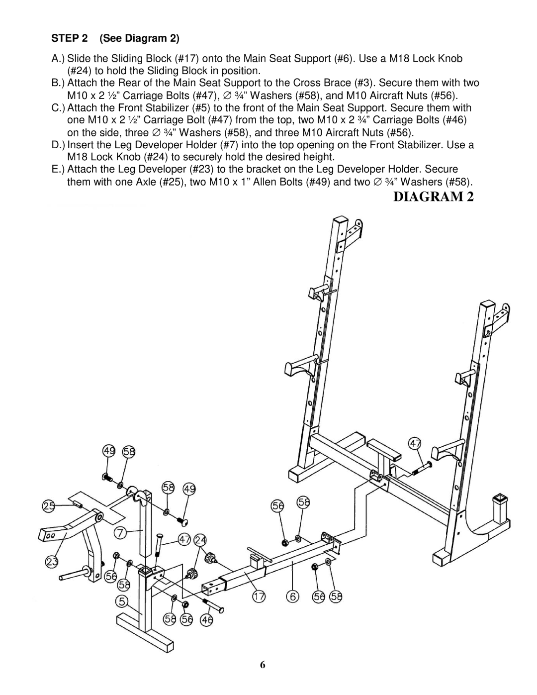
STEP 2 (See Diagram 2)
A.) Slide the Sliding Block (#17) onto the Main Seat Support (#6). Use a M18 Lock Knob (#24) to hold the Sliding Block in position.
B.) Attach the Rear of the Main Seat Support to the Cross Brace (#3). Secure them with two M10 x 2 ½” Carriage Bolts (#47), ∅ ¾” Washers (#58), and M10 Aircraft Nuts (#56).
C.) Attach the Front Stabilizer (#5) to the front of the Main Seat Support. Secure them with one M10 x 2 ½” Carriage Bolt (#47) from the top, two M10 x 2 ¾” Carriage Bolts (#46) on the side, three ∅ ¾” Washers (#58), and three M10 Aircraft Nuts (#56).
D.) Insert the Leg Developer Holder (#7) into the top opening on the Front Stabilizer. Use a M18 Lock Knob (#24) to securely hold the desired height.
E.) Attach the Leg Developer (#23) to the bracket on the Leg Developer Holder. Secure them with one Axle (#25), two M10 x 1” Allen Bolts (#49) and two ∅ ¾” Washers (#58).
DIAGRAM 2
6