ASSEMBLY INSTRUCTION
Tools Required Assembling the Machine: Two Adjustable Wrenches and Allen Wrenches.
NOTE: It is strongly recommended two or more people assembling this machine to avoid possible injury.
STEP 1 (See Diagram 1)
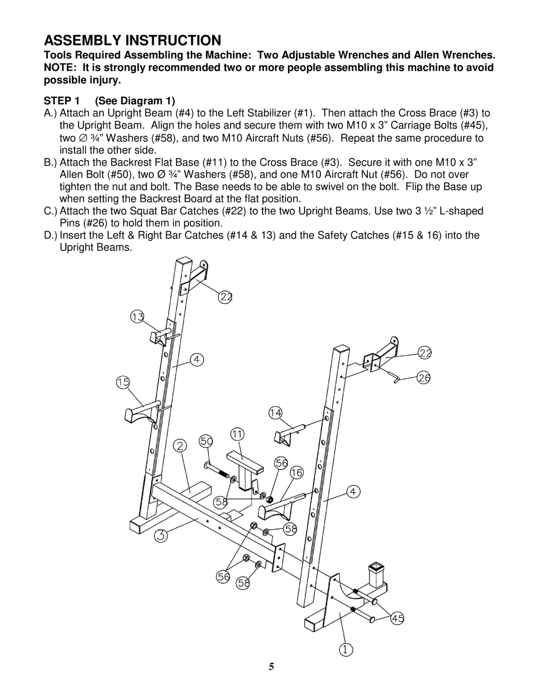
A.) Attach an Upright Beam (#4) to the Left Stabilizer (#1). Then attach the Cross Brace (#3) to the Upright Beam. Align the holes and secure them with two M10 x 3” Carriage Bolts (#45), two ∅ ¾” Washers (#58), and two M10 Aircraft Nuts (#56). Repeat the same procedure to install the other side.
B.) Attach the Backrest Flat Base (#11) to the Cross Brace (#3). Secure it with one M10 x 3” Allen Bolt (#50), two Ø ¾” Washers (#58), and one M10 Aircraft Nut (#56). Do not over tighten the nut and bolt. The Base needs to be able to swivel on the bolt. Flip the Base up when setting the Backrest Board at the flat position.
C.) Attach the two Squat Bar Catches (#22) to the two Upright Beams. Use two 3 ½”
D.) Insert the Left & Right Bar Catches (#14 & 13) and the Safety Catches (#15 & 16) into the Upright Beams.
5