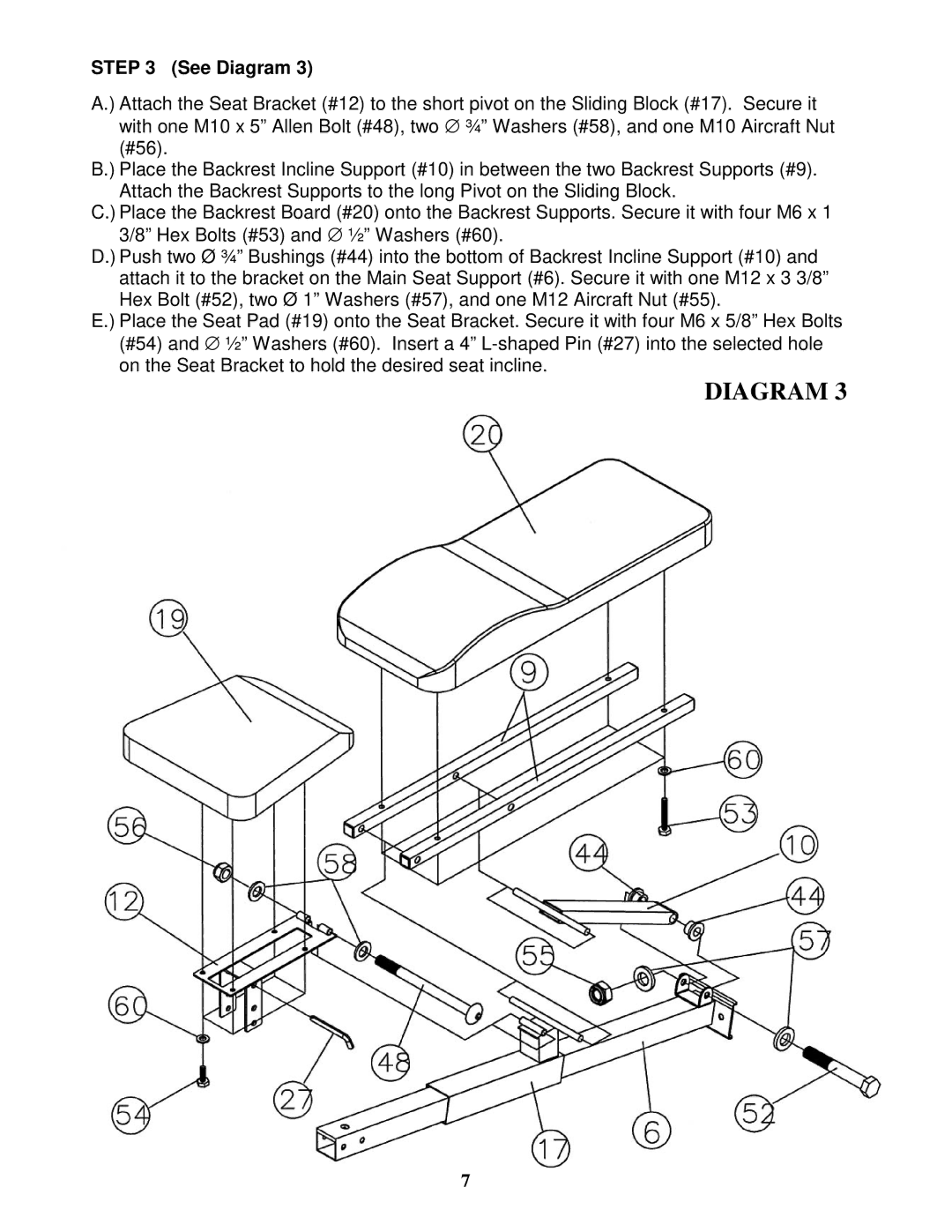
STEP 3 (See Diagram 3)
A.) Attach the Seat Bracket (#12) to the short pivot on the Sliding Block (#17). Secure it with one M10 x 5” Allen Bolt (#48), two ∅ ¾” Washers (#58), and one M10 Aircraft Nut (#56).
B.) Place the Backrest Incline Support (#10) in between the two Backrest Supports (#9). Attach the Backrest Supports to the long Pivot on the Sliding Block.
C.) Place the Backrest Board (#20) onto the Backrest Supports. Secure it with four M6 x 1 3/8” Hex Bolts (#53) and ∅ ½” Washers (#60).
D.) Push two Ø ¾” Bushings (#44) into the bottom of Backrest Incline Support (#10) and attach it to the bracket on the Main Seat Support (#6). Secure it with one M12 x 3 3/8” Hex Bolt (#52), two Ø 1” Washers (#57), and one M12 Aircraft Nut (#55).
E.) Place the Seat Pad (#19) onto the Seat Bracket. Secure it with four M6 x 5/8” Hex Bolts (#54) and ∅ ½” Washers (#60). Insert a 4”
DIAGRAM 3
7