Location and Space Requirements (Cont.)
CAST IRON STOVE AND
Stove Body Assembly
5
PRE-INSTALLATION
PREPARATION
Continued
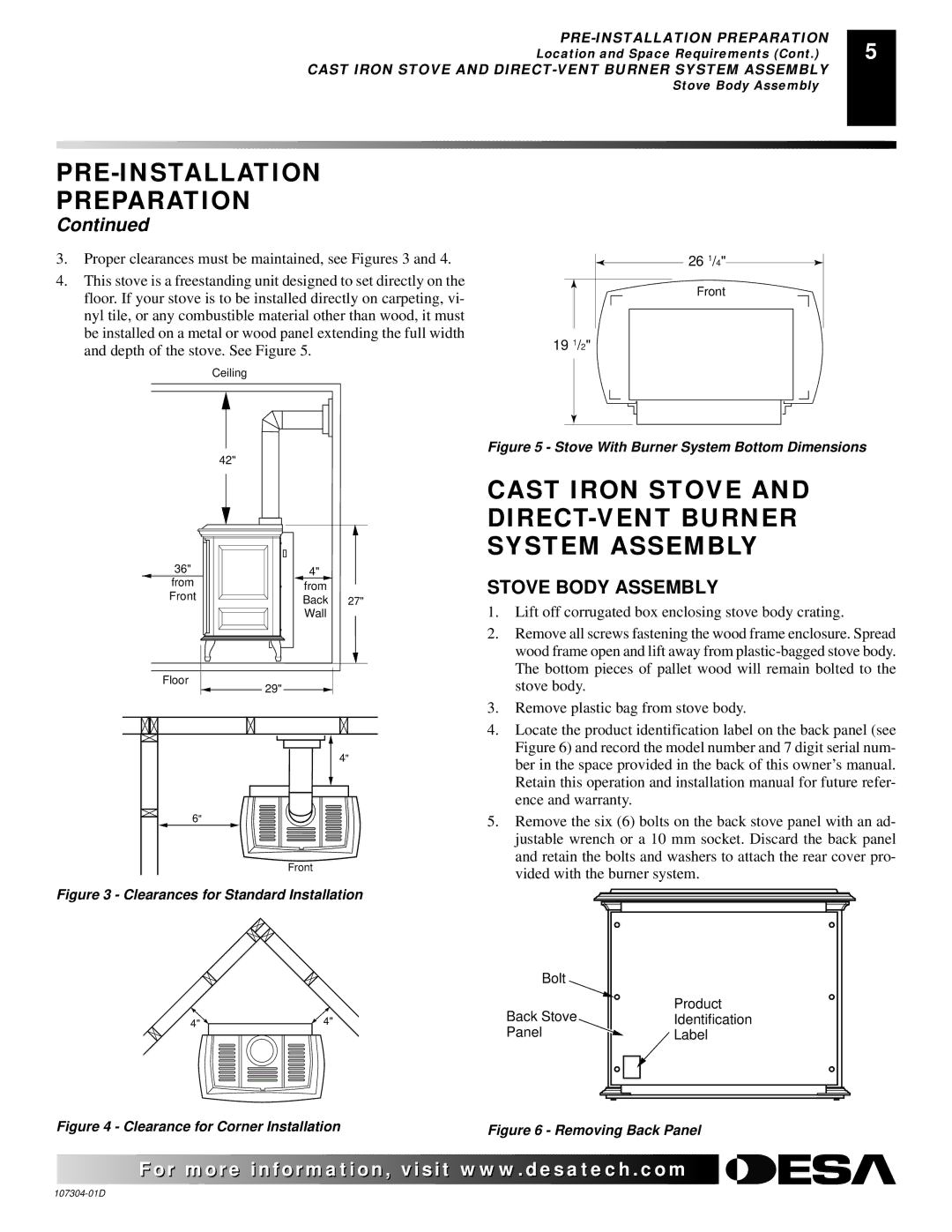
3. Proper clearances must be maintained, see Figures 3 and 4.
4. This stove is a freestanding unit designed to set directly on the |
|
|
|
|
|
|
|
| |
floor. If your stove is to be installed directly on carpeting, vi- |
|
|
|
|
nyl tile, or any combustible material other than wood, it must |
|
|
|
|
be installed on a metal or wood panel extending the full width |
|
|
|
|
19 1/2" |
| |||
and depth of the stove. See Figure 5. |
| |||
|
|
|
| |
Ceiling |
|
|
|
|
|
|
|
|
|
|
|
|
|
|
26 1/4"
Front
42"
36"
from
Front
4"
from
Back 27" Wall
Figure 5 - Stove With Burner System Bottom Dimensions
CAST IRON STOVE AND DIRECT-VENT BURNER SYSTEM ASSEMBLY
STOVE BODY ASSEMBLY
1. | Lift off corrugated box enclosing stove body crating. |
2. | Remove all screws fastening the wood frame enclosure. Spread |
| wood frame open and lift away from |
| The bottom pieces of pallet wood will remain bolted to the |
Floor |
29" |
4" |
6" |
Front |
Figure 3 - Clearances for Standard Installation
| stove body. | ||||
3. | Remove plastic bag from stove body. | ||||
4. | Locate the product identification label on the back panel (see | ||||
| Figure 6) and record the model number and 7 digit serial num- | ||||
| ber in the space provided in the back of this owner’s manual. | ||||
| Retain this operation and installation manual for future refer- | ||||
| ence and warranty. | ||||
5. | Remove the six (6) bolts on the back stove panel with an ad- | ||||
| justable wrench or a 10 mm socket. Discard the back panel | ||||
| and retain the bolts and washers to attach the rear cover pro- | ||||
| vided with the burner system. | ||||
|
|
|
|
|
|
|
|
|
|
|
|
4" ![]()
Bolt
4" | Back Stove | |
Panel | ||
|
Product
Identification
![]() Label
Label
Figure 4 - Clearance for Corner Installation | Figure 6 - Removing Back Panel |
![]() For more
For more![]()
![]()
![]() visit www.
visit www.![]()
![]()
![]() .com
.com![]()
![]()
![]()
![]()
![]()
