8
CAST IRON STOVE AND
Installing
Installing Optional Blower Accessory
CAST IRON STOVE AND DIRECT-VENT BURNER SYSTEM ASSEMBLY
Continued
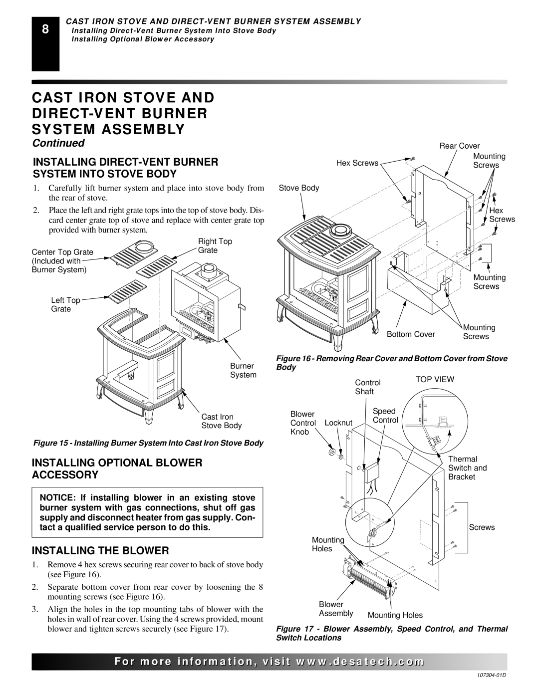
INSTALLING DIRECT-VENT BURNER SYSTEM INTO STOVE BODY
1.Carefully lift burner system and place into stove body from the rear of stove.
2.Place the left and right grate tops into the top of stove body. Dis- card center grate top of stove and replace with center grate top provided with burner system.
Hex Screws ![]()
![]()
Stove Body
Rear Cover
Mounting
Screws
Hex
![]() Screws
Screws
Center Top Grate ![]() (Included with
(Included with ![]()
![]()
![]() Burner System)
Burner System)![]()
Left Top ![]()
![]()
Grate
Right Top ![]() Grate
Grate
Mounting
Screws
Bottom Cover | Mounting |
Screws |
Burner
System
Cast Iron
Stove Body
Figure 15 - Installing Burner System Into Cast Iron Stove Body
INSTALLING OPTIONAL BLOWER
ACCESSORY
NOTICE: If installing blower in an existing stove burner system with gas connections, shut off gas supply and disconnect heater from gas supply. Con- tact a qualified service person to do this.
INSTALLING THE BLOWER
1.Remove 4 hex screws securing rear cover to back of stove body (see Figure 16).
2.Separate bottom cover from rear cover by loosening the 8 mounting screws (see Figure 16).
3.Align the holes in the top mounting tabs of blower with the holes in wall of rear cover. Using the 4 screws provided, mount blower and tighten screws securely (see Figure 17).
Figure 16 - Removing Rear Cover and Bottom Cover from Stove Body
| Control | TOP VIEW |
|
| |
| Shaft |
|
Blower | Speed |
|
Control |
| |
Control Locknut |
| |
|
| |
Knob |
|
|
|
| Thermal |
|
| Switch and |
|
| Bracket |
Screws
Mounting
Holes
Blower |
|
Assembly | Mounting Holes |
Figure 17 - Blower Assembly, Speed Control, and Thermal Switch Locations
![]()
![]()
![]()
![]()
![]() For
For![]()
![]()
![]()
![]()
![]()
![]()
![]()
![]()
![]()
![]()
![]()
![]()
![]() .
.![]()
![]()
![]()
![]() .com
.com![]()
![]()
![]()
![]()
![]()