22
STOVE AND
Checking Gas Connection (Cont.)
Installing Optional Wall Mount Switch - GWMS2
STOVE AND DIRECT-VENT BURNER SYSTEM INSTALLATION
Continued
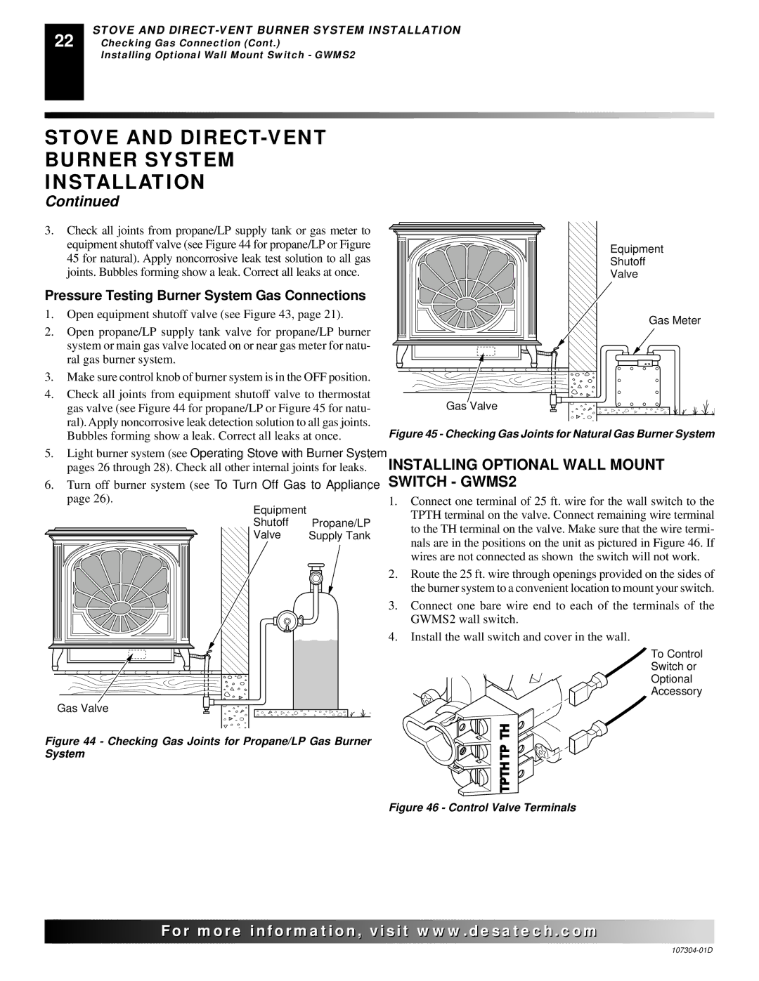
3.Check all joints from propane/LP supply tank or gas meter to equipment shutoff valve (see Figure 44 for propane/LP or Figure 45 for natural). Apply noncorrosive leak test solution to all gas joints. Bubbles forming show a leak. Correct all leaks at once.
Pressure Testing Burner System Gas Connections
1. | Open equipment shutoff valve (see Figure 43, page 21). |
2. | Open propane/LP supply tank valve for propane/LP burner |
| system or main gas valve located on or near gas meter for natu- |
| ral gas burner system. |
3. | Make sure control knob of burner system is in the OFF position. |
4. | Check all joints from equipment shutoff valve to thermostat |
| gas valve (see Figure 44 for propane/LP or Figure 45 for natu- |
| ral). Apply noncorrosive leak detection solution to all gas joints. |
Gas Valve |
Equipment
Shutoff
Valve
Gas Meter
| Bubbles forming show a leak. Correct all leaks at once. |
5. | Light burner system (see Operating Stove with Burner System, |
| pages 26 through 28). Check all other internal joints for leaks. |
6. | Turn off burner system (see To Turn Off Gas to Appliance, |
| page 26). |
Equipment |
|
Shutoff | Propane/LP |
Valve | Supply Tank |
Gas Valve |
|
Figure 44 - Checking Gas Joints for Propane/LP Gas Burner System
Figure 45 - Checking Gas Joints for Natural Gas Burner System
INSTALLING OPTIONAL WALL MOUNT SWITCH - GWMS2
1.Connect one terminal of 25 ft. wire for the wall switch to the TPTH terminal on the valve. Connect remaining wire terminal to the TH terminal on the valve. Make sure that the wire termi- nals are in the positions on the unit as pictured in Figure 46. If wires are not connected as shown the switch will not work.
2.Route the 25 ft. wire through openings provided on the sides of the burner system to a convenient location to mount your switch.
3.Connect one bare wire end to each of the terminals of the GWMS2 wall switch.
4.Install the wall switch and cover in the wall.
To Control
Switch or
Optional
Accessory
TPTH TP TH
Figure 46 - Control Valve Terminals
![]()
![]()
![]()
![]()
![]() For
For![]()
![]()
![]()
![]()
![]()
![]()
![]()
![]()
![]()
![]()
![]()
![]()
![]() .
.![]()
![]()
![]()
![]() .com
.com![]()
![]()
![]()
![]()
![]()