VENTING INSTALLATION
Installation for Vertical Termination (Cont.)
17
VENTING INSTALLATION
Continued
6.Continue to add pipe sections until the height of the vent cap meets the minimum building code requirements described in Figure 21 on page 11. Note: You must increase vent height for steep roof pitches. Nearby trees, adjoining rooflines, steep pitched roofs, and other similar factors may cause poor draft or
7.
Note: If the vent pipe passes through any occupied areas above the first floor, including storage spaces and closets, you must enclose pipe. You may frame and sheetrock the enclosure with standard construction material. Make sure and meet the minimum allowable clearances to combustibles. Do not fill any of the required air spaces with insulation.
Cathedral Ceiling Installation
1.Remove shingles or other roof covering as necessary to cut the rectangular hole for the support box. Mark the outline of the cathedral ceiling support box on the roof sheathing using the locating hole as a center point.
2.Cut the hole 1/8" larger than the support box outline (see Figure 34).
3.Lower the support box through the hole in the roof until the bottom of the box extends at least 2" below the ceiling (see Figure 34). Align the support box vertically and horizontally using a level. Temporarily tack the support box in place through the inside walls and into the roof sheathing.
4.Using tin snips, cut the support box from the top corners down to the roofline and fold the resulting flaps over the roof sheath- ing (see Figure 35). Apply a bead of nonhardening mastic around the top edges of the support box to make a seal between the box and the roof. Nail in place with roofing nails. Remove any com- bustible material that might be inside of the support box.
5.Complete the cathedral ceiling installation by following the same procedures outlined in steps 2 through 7 for Flat Ceiling Instal- lation, starting page 16.
Level![]()
![]()
Cathedral Ceiling
![]() Support Box
Support Box
2" minimum below finished ceiling
Cut hole 1/8" larger than support box when projected onto roofline
Figure 34 - Cathedral Ceiling Support Box Installation
![]() Nonhardening mastic under all edges of support box before nailing
Nonhardening mastic under all edges of support box before nailing
Figure 35 - Installed Cathedral Ceiling Support Box
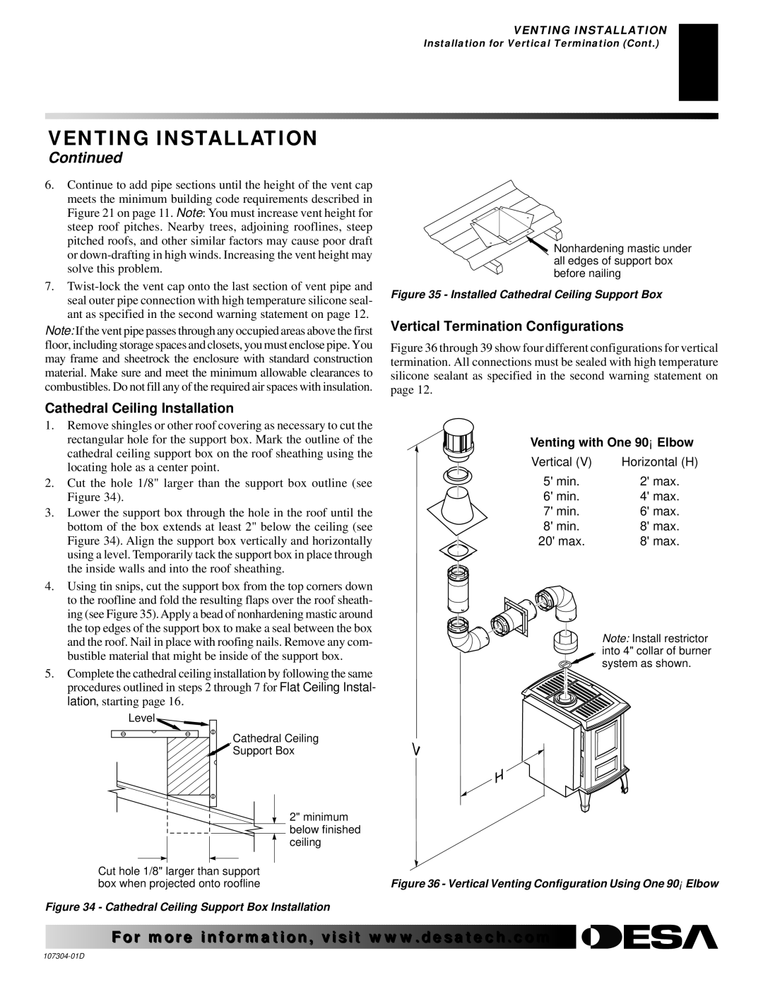
Vertical Termination Configurations
Figure 36 through 39 show four different configurations for vertical termination. All connections must be sealed with high temperature silicone sealant as specified in the second warning statement on page 12.
Venting with One 90° Elbow
Vertical (V) | Horizontal (H) |
5' min. | 2' max. |
6' min. | 4' max. |
7' min. | 6' max. |
8' min. | 8' max. |
20' max. | 8' max. |
Note: Install restrictor into 4" collar of burner system as shown.
Figure 36 - Vertical Venting Configuration Using One 90° Elbow
For more![]()
![]()
![]() visit www.
visit www.![]()
![]()
![]() .com
.com![]()
![]()
![]()
![]()
![]()