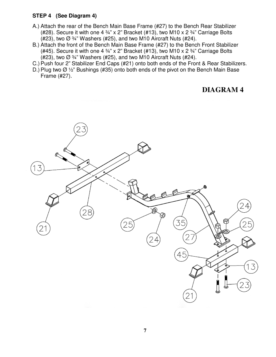
STEP 4 (See Diagram 4)
A.) Attach the rear of the Bench Main Base Frame (#27) to the Bench Rear Stabilizer (#28). Secure it with one 4 ¾” x 2” Bracket (#13), two M10 x 2 ¾” Carriage Bolts (#23), two Ø ¾” Washers (#25), and two M10 Aircraft Nuts (#24).
B.) Attach the front of the Bench Main Base Frame (#27) to the Bench Front Stabilizer (#45). Secure it with one 4 ¾” x 2” Bracket (#13), two M10 x 2 ¾” Carriage Bolts (#23), two Ø ¾” Washers (#25), and two M10 Aircraft Nuts (#24).
C.) Push four 2” Stabilizer End Caps (#21) onto both ends of the Front & Rear Stabilizers. D.) Plug two Ø ½” Bushings (#35) onto both ends of the pivot on the Bench Main Base
Frame (#27).
DIAGRAM 4
7
