| Instructions for the fitter | |
GB | ||
| ||
| Mounting the wooden panel onto the door and in- | |
| ||
| serting the machine into cabinets: | |
| In the case where the machine must be shipped for final | |
| installation after the wooden panel has been mounted, we | |
| suggest leaving it in its original packaging. The packaging | |
| was designed to make it possible to mount the wooden | |
| panel onto the machine without removing it completely (see | |
| figures below). | |
| The wooden panel that covers the face of the machine must | |
| not be less than 18 mm in thickness and can be hinged on | |
| either the right or left. For the sake of practicality when using | |
| the machine, we recommend that the panel be hinged on | |
| the same side as the door for the machine itself - the left. |
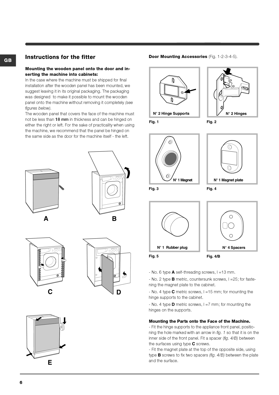
Door Mounting Accessories (Fig.
| N° 2 Hinge Supports |
|
|
|
|
|
|
|
|
|
|
|
|
|
|
|
|
| |
|
|
|
|
|
|
|
|
| |
|
|
|
|
|
|
|
|
| |
|
|
|
|
|
|
|
|
| |
|
|
|
|
|
|
|
|
| |
|
|
|
|
|
|
|
|
| |
|
|
|
| N° 2 Hinges | |||||
|
|
|
|
|
|
|
|
|
|
|
|
|
|
|
|
|
|
|
|
Fig. 1 | Fig. 2 | ||||||||
N° 1 Magnet | N° 1 Magnet plate |
Fig. 3 | Fig. 4 |
AB
CD
E
| N° 1 Rubber plug |
| N° 4 Spacers |
|
|
|
|
|
|
|
|
Fig. 5 | Fig. 4/B | ||
-No. 6 type A
-No. 2 type B metric, countersunk screws, l =25; for faste- ning the magnet plate to the cabinet.
-No. 4 type C metric screws, l =15 mm; for mounting the hinge supports to the cabinet.
-No. 4 type D metric screws, l =7 mm; for mounting the hinges on the supports.
Mounting the Parts onto the Face of the Machine.
- Fit the hinge supports to the appliance front panel, positio- ning the hole marked with an arrow in fig. 1 so that it is on the inner side of the front panel. Fit a spacer (fig. 4/B) between the surfaces using type C screws.
-Fit the magnet plate at the top of the opposite side, using type B screws to fix two spacers (fig. 4/B) between the plate and the surface.
6